background image


  1 of 3   


About this Manual

 ................................................................................................................................... 3


Overview of the System

 ......................................................................................................................... 4


Characteristics of the System

................................................................................................................ 4


Configuration of the System

 .................................................................................................................. 5


1.


PAVA6500/PAVA6500E (Control Host/Extended Host)

 ..................................................................... 5


1.1.


Front Panel .................................................................................................................................. 6


1.2.


Rear Panel ................................................................................................................................. 10


1.3.


Technical Specification ............................................................................................................. 15


Electrical Indicators

 ................................................................................................................ 15


Mechanical Indicators

 ............................................................................................................ 16


Environment Requirements

 .................................................................................................. 16


2.


Business MIC——PAVA6006

 .............................................................................................................. 17


1.4.


Front/Rear Panels...................................................................................................................... 17


1.5.


Technical Specification ............................................................................................................. 20


Electrical Indicators

 ................................................................................................................ 20


Mechanical Indicators

 ............................................................................................................ 20


Environment Requirements

 .................................................................................................. 20


3.


Wiring Diagram of the System

 ............................................................................................................ 21


4.


Routine Operation

 ................................................................................................................................. 21


4.1.


Host Lines 01-06 for Manual Playing

 .......................................................................................... 22


4.2.


Manual Playing of EVAC Voice

 .................................................................................................... 22


4.3.


Automatic Triggering of EVAC Voice

 .......................................................................................... 22


4.4.


PAVA6000 Operation

 ..................................................................................................................... 23


4.5.


Paging Operation Using Emergency Microphone

 .................................................................... 24


4.6.


Operations in PAVA6006 are as follows

 ..................................................................................... 24


Software Introduction (PAVA6000)

 ..................................................................................................... 24


Description of Icons in the Software

 ................................................................................................... 24


Note: HOST 01 represents the system host, namely, PAVA6500, and the extended host 1 is: HOST 

02 Initialize

 ..................................................................................................................................................... 25


2.


Initialization

 ............................................................................................................................................. 26


2.1.


Computer configuration ............................................................................................................ 26


2.2.


Installation ................................................................................................................................ 26


2.3.


Uninstall .................................................................................................................................... 28


2.4.


Operation .................................................................................................................................. 28


2.4.1.


Software Login

 ................................................................................................................ 28


2.4.2.


Introduction of Control Interface

 ................................................................................... 30


2.4.2.1.


Introduction of Menu Bar and Tools .................................................................. 30


2.4.3.


Introduction of “Current Operating Interface Selection”

............................................ 31


2.4.3.1.


Partition Control ................................................................................................ 31


2.4.3.2.


System Equipment State (STATE) ..................................................................... 33


2.4.3.3.


SYSTEM CONFIGURATION .......................................................................... 34


2.4.3.3.1.


Check the Detailed Configuration Parameters of the System 

Equipment

  34


2.4.3.3.2.


Fire Rules

 .................................................................................................. 37


Summary of Contents for PAVA6000

Page 1: ...Operation Manual for PAVA6500 System Guangzhou DSPPA Audio Co Ltd PAVA6500 PAVA6500E PAVA6006 PAVA6000 ...

Page 2: ...tic Triggering of EVAC Voice 22 4 4 PAVA6000 Operation 23 4 5 Paging Operation Using Emergency Microphone 24 4 6 Operations in PAVA6006 are as follows 24 Software Introduction PAVA6000 24 Description of Icons in the Software 24 Note HOST 01 represents the system host namely PAVA6500 and the extended host 1 is HOST 02 Initialize 25 2 Initialization 26 2 1 Computer configuration 26 2 2 Installation ...

Page 3: ... of 3 2 4 3 3 3 Grouping Configuration of the System 38 2 4 3 3 4 Configuration of Audio Priority of the System 39 2 4 3 4 Log Query of Equipment Modules 40 2 4 3 5 OTHER Other settings 41 Precautions 43 ...

Page 4: ...m Target Users Users and Installers of PAVA6500 Voice Alarm System Terminology System Host PAVA6500 Extended Host PAVA6500E Business MIC PAVA6006 Control Software PAVA6000 Note The software functions of this system will continue to upgrade but it will be backward compatible so please pay an attention to the real time information of the website of the Company ...

Page 5: ...ntrol and Indicating Equipment Standard EN54 16 Automatic system fault diagnosis data backup redundant line and record fault status 5000 records are safe stable and reliable Compatible with the wiring standard of 3 wire and 4 wire systems Built in emergency voice message and tone information The user can freely replace them according to the site environment language and their fancies Programmed to...

Page 6: ...but also can realize the evacuation guidance on the site via the handheld microphone and control the emergency calls and business broadcasting of up to 120 partitions as well as the play of background music Handheld microphone is available for site evacuation in case of any emergency Built in EVAC voice message and Chimes Management for a real time monitoring Notes 1 Audio message format extension...

Page 7: ...artitions cannot exceed 500W Available for external connection of 6 line inputs to play the background music Support event linkage and partition output up to 3000 status records of equipment modules including power module handheld microphone module voice message module power amplifier module speaker circuit module etc please consult the related descriptions in PAVA6000 Able to simultaneously conne...

Page 8: ...l down indicates that the system is not configured 3 Connection Status Indicator of Host Extended Host Yellow indicating that the current extended host does not establish the logical or physical connection with the host Die out OFF indicating that the current host does not establish the logical or physical connection with PAVA6000 Green Indicating that the current equipment is connected normally 4...

Page 9: ...rtition output Note no matter whether it is a manual entry exit or automatic entry exit its execution time and way can be checked in the LOG of PAVA6000 8 Multi purpose Reset Key ACK RESET Answering System Status a if various system modules work normally or when the diagnosis of system modules is abnormal but FAULT indicator light does not flash no treatment is made to the equipment after pressing...

Page 10: ...tion will then be recorded and it will be informed to the user in the form of sound and light The detection sensitivity of partitions partitions is equal to or greater than 20W 14 Partition PTT or Remote Business Microphone Paging Indication Note for a paging service the user can manually close the partitions that are not call or increase the new partitions 15 Indication that the Partition is Broa...

Page 11: ...monitoring speaker output volume Note the host can monitor the current output audio which can be adjusted by this knob 21 Adjustment of Handheld Microphone Output Sensitivity 22 Adjustment of Handheld Microphone Sensitivity Adjust the handheld microphone output sensitivity 22 23 Adjustment of Audio Volume 24 Adjustment of Total Output Volume of Partitions 1 2 Rear Panel 2 3 4 1 5 6 7 8 9 19 18 16 ...

Page 12: ...ker A B Circuit Output Interfaces Connect the constant pressure speaker or 3 wire audio control system Output voltage is 0 100V Note please make at least one modeling of the speaker circuit after completing the wiring It will be OK to suspend the partition that is not connected with the speaker Of course its output can also be prohibited in PAVA6000 the related operations refer to the related chap...

Page 13: ...ort the computer to directly connect PAVA6000 device and automatically recognize the crossover and straight through network Of course in order to unify the network cables of five categories of the system they can all consult the TIE EIA 568B standards including the connection of PAVA6500E with PAVA6006 7 Main Backup Interfaces of Business Microphone Used to connect PAVA6006 Support the closed and ...

Page 14: ... loss of message while replacing and formatting the SD card 5 The number of three audio files stored in the folder shall not exceed 255 When it exceeds this number only 255 audios are valid 10 11 Backup Power Amplifier Interface 10 power signal inputs 11 audio signal output Attention shall be paid to that it is a balanced output herein 12 Relay Fault Status Output Interface of the System In case o...

Page 15: ...dance test ENABLE means to start the speaker circuit impedance test and conversely close the speaker circuit impedance test refer to 13 speaker partition status indicator 16 MIC or Line Input Interface Connect MIC or line audio input signals 17 Adjustment of MIC Line Input Audio Sensitivity to be operated in combination with 16 18 and 19 18 Line Input Interface to be Operated in combination with 1...

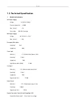
Page 16: ...ne Sensitivity 5mV Impedance 600Ω Caron Input Distortion 1 Rated output power 1kHz Sensitivity 775mV Impedance 10kΩ Signal Noise Ratio SNR 70dB Line Input Distortion 1 Rated output power 1kHz Sensitivity 775mV Impedance 10kΩ Signal noise ratio 70dB Audio Output Distortion 1 Rated output power 1kHz Sensitivity 0dBmV Signal noise ratio 70dB System Connection Control Contact Output Input I O System f...

Page 17: ... mode no voltage short circuit Voice Message Data format WAV Memory type SD card Message number 255 3 Retention 10 years Log Information Data format HEX Memory type Nand Flash Message Number 1000 Retention 10years Mechanical Indicators Size length x width x depth 484 132 449 mm 3U Net Weight 11 5kg or so Installation Desktop or 19inch rack Color Black Environment Requirements Operating Temperature...

Page 18: ...rouping selection in a key It is easy to operate and it is intuitive and clear Key mode and PTT mode for paging can be configured Paging priority can be configured Support 24V phantom power supply It is not necessary to provide the external power supply adapter use the balanced transmission to extend the transmission distance 600m Support the redundant cabling of the line 1 4 Front Rear Panels 4 6...

Page 19: ... work currently and in a ready state 4 Key for Partition Selection to be operated in combination with the above 3 When there is no paging in MIC and the left LED light is Always ON or dies out the corresponding LED lights will flash after pressing the corresponding keys which indicates that the user has selected this partition When MIC is paging currently the corresponding key is pressed or held d...

Page 20: ...be ended by pressing this key 2 When there is no paging but the partition is selected it will begin the paging by pressing this key it will wait for the ON of the microphone light Attentions When the MIC is operated in the PTT mode this key shall be always held down for a paging operation otherwise the paging will end PTT mode refers to the description in the later 11 7 MIC Power Switch It is used...

Page 21: ... is detected all LED lights on the panel will automatically restore to their normal display states after lighting in an order of Red Green Yellow It is used mainly to test whether the display of LED lights is normal or not 1 5 Technical Specification Electrical Indicators Phantom Power Supply Voltage 20V 27 5V Max Current 0 1A 24Vpower supply lighting of all panel LED lights in a paging state Powe...

Page 22: ...of 3 3 Wiring Diagram of the System 4 Routine Operation Devices PAVA6500 PAVA6500E PAVA6006 PAVA6000 The electrical connections among the system equipment or devices are correct and the operation is normal ...

Page 23: ...ergency LED press it to make the LED to flash in a rhythm Select the output partitions the method is identical to the above Host Line 01 06 for Manual Playing In the manual mode it is impossible to select the partitions of extended host on the host panel The automatic mode or PAVA6006 or PAVA6500FM is available Select the outputted EVAC Voice it will be OK when the corresponding LED lights of EVAC...

Page 24: ...as only configured the Group 2 of the host only Partition 2 is displayed in the list box in the right Way 2 Single partition operation this operation is only to singly open or close the partition and it cannot control the type of current output audio Click the above of corresponding partition name a button will appear click this button to control this partition as shown in the following figure Ste...

Page 25: ...ing is available if it is operated in the PTT mode please do not release the button CALL Press again the button CALL to end the paging operation it is only required to release the button for the PTT mode Note the selections on the panel for the grouping and zoning operations are the same and only the final execution outcomes are different Software Introduction PAVA6000 Description of Icons in the ...

Page 26: ...t partition is operating Current partition impedance is changing open circuit or short circuit Current partition is normal and no audio is playing Current partition is playing EVAC voice message Current system module works normally Current system module is in trouble Indicating that the current host works normally Indicating that the current host is in trouble ...

Page 27: ...s comprehensively enhanced its security performance please ensure to log in the operating system with an identity of administrator otherwise it may lead to the error during the software installation and during the running after installation Please check whether the administrator authority is obtained before running method is as follows Find the icon on the desktop click the right mouse button to s...

Page 28: ...terface of user so please select the network connection communicating currently with the host Click the right mouse button to select Properties and find Item Internet Protocol Version 4 TCP IPv4 in the listbox and then click the Properties in the lower right corner for modification and finally click the OK When the user computer uses the dynamic ID address the operation method is as follows if the...

Page 29: ...start to establish the connection with the host upon the network parameters modified by the user 2 3 Uninstall Please enter the Programs Features in control panel to find the corresponding PAVA6500 and then click and confirm it 2 4 Operation 2 4 1 Software Login 1 Double click the icon on the desktop to enter the main menu of the software as shown in the following figure ...

Page 30: ...utomatically 3 The logical connection between PAVA6000 and PAVA65000 is as follows 4 Enter the following interface after syncing the system parameters Fig 1 Note In the above figure in its top is the system menu and toolbar at the left side is the selection items of current operation interface in the middle portion is the detailed operation items of current selection interface of the user at the r...

Page 31: ...ration saved by the user and it is equivalent to the icon in the toolbar Save is used to save the LOG message of system modules or user s configuration and it is equivalent to the icon in the toolbar Login and Exit means the login or exit from the PAVA6000 and it is equivalent to the icon in the toolbar View Menu is an Interface and it is used to customize the personalized display appearance for t...

Page 32: ...reater the percentage is the lower the accuracy will be 2 4 3 1 Partition Control Login the software or click the CONTROL at left side display as shown in the above Fig 1 The user information is provided in the above figure interface On the central left side it displays that there are six groups using the PAVA6000 controllable system On the central right side it displays that the current system ha...

Page 33: ...ed or closed If the yellow LED is ON the user can have a check in the pop up window by double clicking the corresponding device items after clicking the STATE column at the left side Operation and Control Operations of Specified Host and Specified Zones are as follows Output the specified audio or close the zones Move the mouse pointer onto the PARTITION 0X at the right side of HOST ID on the cent...

Page 34: ...IONS in the lower right corner use the mouse to click ENABLE audio in EVAC MESSAGE needing the emergency status or LINE INPUT AUDIO on the right side Close the Groups 1 Select the target partitions 2 select output audio use the mouse to click ENABLE audio in EVAC MESSAGE needing the emergency status or LINE INPUT AUDIO on the right side 2 4 3 2 System Equipment State STATE The column STATE EQUIPME...

Page 35: ...ponding speaker of CIE loop namely it is detected that the impedance of the speaker circuit exceeds 10 30 and the short circuit of the partition is to disable the control of this partition in order to protect the amplifier the host will automatically disable the output until the trouble is shot or the cable between the equipment and CIE loop is in a short circuit if the current equipment contact i...

Page 36: ...SE the serial number of files saved in prompt folder in SD card namely serial number of bell voices of which indicates the startup and indicates no start The user may Enable or Disable single partition of the host or extended host according to the actual conditions When the check box of the partitions of PARTITION ENABLE CONFIGURATION is which indicates the ENABLE and which indicates the DISABLED ...

Page 37: ... is no drop down box in the chart in the listbox and then click OK Otherwise the modification made just now shall be invalid Similarly the user can set up the switch of each microphone and specify different prompt tone bell voice through the Paging Prompt Tone Switch and the method is identical to that of the previous microphone of host panel which will not be described here the setting of many mi...

Page 38: ...ition and online relay status Click the Item Fire mode as shown below In the above figure the user can select Specify Partition or All partition from the drop down box on the right side of Alarm mode 1 Specify partition means that the system will only play EVAC voice message to the specified partition of corresponding contact and close the output to other partitions when the system has detected th...

Page 39: ...ouping groups shall be manually operated and the contact is mostly used for the linkage via the third party system in case of uncertainty factors or any emergency 2 The grouping operation does not contain the relay output but the contact contains the relay output which is easy or convenient to control the third party system to realize the linkage Precaution after completing the modification please...

Page 40: ...h the intermediate operation button and are the operation of single partition or zone is to add the system partitions on the left into the current groups and means an reverse operation namely delete the selected partition from the current groups and are to delete all partition of current groups and add all current system partitions into the current group respectively Precaution after completing th...

Page 41: ...as cfg files for backup by clicking 2 The user can import the backup system configuration parameters through the it is required to manually synchronize them after the import 2 4 3 4 Log Query of Equipment Modules Click LOG as shown below Notes ID is a random number without practical significance CALENDAR refers to the date of recording this module LOG TYPE refers to the type of this log it is used...

Page 42: ...password Notes USER NAME refers to the user name for current user to log in the system Double click to enter the edit mode PASSWORD refers to the user password for current user to log in the system Double click to enter the edit mode Precaution after completing the modification please click the Application Otherwise your setting cannot achieve your expected purpose in the corresponding equipment 2...

Page 43: ...ur expected purpose in the corresponding equipment 3 Adjust Impedance Error of System Speaker Partitions Click EVAC system timing and select the error range allowed by current speaker circuit in the pop up window drop down list box it can appropriately increase this percentage in case of any error report of speaker circuit ...

Page 44: ...ion 5 The remote microphone PAVA6006 provides the 24V phantom power supply Please shorten the length of cables when the PAVA6500 indicator light becomes darker or fails to work normally it is normal for five types of wires cables after field test of 600m it is noted that this length of 600m refers to the total length of loop rather than the length of single equipment or device 6 The main system eq...

Reviews: