14 of 3
”3” represents the trigger mode configuration ID. When it is in “ENABLE”, it is triggered by using the relay short
circuit. “DISABLED” means the triggering by way of level.
“4” represents the configuration ID of backup amplifier. “ENABLE” refers to the configured backup amplifier and
“DISABLED” refers to the backup amplifier not configured;
“5” refers to selection mode of host IP address. “ENABLE” means the IP address of host will use the IP address
automatically allocated by the router, and “DISABLED” means that the host will use the static IP address;
Consult the above “6 – Ethernet Port”;
“6” means to reset the host IP address to its default value: IP address is 192.168.1.168, and port number is
16888.
“7” represents the speaker circuit impedance calibration ID (refer to front panel “13 – speaker partition status
indicator”). Please ensure that the current partitions are all closed while calibrating the modeling;
“8” represents the ENABLE ID of speaker circuit impedance test. “ENABLE” means to start the speaker circuit
impedance test, and conversely, close the speaker circuit impedance test (refer to “13 – speaker partition status
indicator”).
○
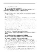
,16 —— MIC or Line Input Interface
Connect MIC or line audio input signals.
○
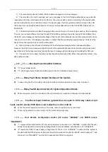
,17 —— Adjustment of MIC/Line Input Audio Sensitivity, to be operated in combination with
“16,18 and 19”
○
,18
—— Line Input Interface, to be Operated in combination with “”17
○
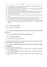
,19 —— Host Output Audio Interface
This interface will output the audio of current amplifier.
Please guarantee the input audio volume to make sure that the signal is not too small or distorted. Please
refer to the parameter description of the whole machine.
○
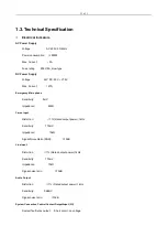
,20 —— Module Configuration Switch of Extended Host (UP means “ENABLE” and DOWN
means “DISABLED”)
Bits “1-5” represent the equipment online ID;
Bit “6” represents DC power supply configuration. “ENABLE” means it will be configured and “DISABLED”
means it will not be configured;
Bit “7” represents the configuration of backup amplifier. “ENABLE” means it will be configured and “DISABLED”
means it will not be configured;
Bit “8” represents speaker circuit monitoring switch. “ENABLE” means the ON and “DISABLED” means the
OFF.


