


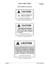
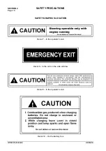


SAFETY PRECAUTIONS
SECTION 2
Page 9
DRESSTA
OM515C520C99/1E
GENERAL MAINTENANCE PRECAUTIONS
Before working on the hydraulic system, be sure the system pressure is relieved. To do so lower the
bucket on the ground, move boom control lever in float position and switch off the engine.
Do not use hands to search for hydraulic leaks. Hydraulic oil escaping under pressure from a very
small hole can be almost invisible yet have sufficient force to penetrate the skin. Use a piece of
cardboard or wood to search for suspected leaks. If injured by escaping oil, see a doctor immediately
because of the possibility of infection or reaction to the oil.
Never work or walk under a raised bucket without proper blocking.
Use extra caution when adjusting the loader's bucket leveler or boom kick-out. Use two trained people
and guard against accidental movement of the machine or loader linkage.
The roll-over protective structure ROPS provides operator protection in the event of machine rollover
or upset. It is designed to bend during a rollover to protect the operator from sudden impact loads. Do
not attempt to repair a ROPS after an accident. Repaired structures do not provide the original
strength and protection. Contact the Authorized Distributor of Construction Equipment for information
on ROPS (or cab) replacement. Do not operate the machine again until the ROPS has been replaced.
Periodically inspect the ROPS for fatigue cracks. Cracks indicate a weakened structure which should
be replaced for your protection. Bolts fastening cab or ROPS must be torqued to
a specific value. Do not cut, grind, weld, drill or tap holes in the ROPS This could weaken the structure
or affect the overall energy absorption capability. Always wear the seat belt during all operation in
order to realize protection of the ROPS (or cab).
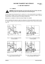
When transporting the machine, lock the frame halves together with the frame locking bar and pins.
Corrosion inhibitors are volatile and flammable. Use them only in a well ventilated area. Keep flames
and sparks away. Do not smoke. Store container in a cool, well ventilated place.
For your safety never push or tow a disabled machine farther than absolutely necessary. When using
a chain or cable, be sure it is strong enough for the expected load and properly secured to the drawbar
pin or towhook. Avoid kinking. Do not pull with a kinked chain or cable because the high stresses could
cause failure in a kinked area. Wear heavy gloves when handling chain or cable. When pulling with a
chain or cable, take up the slack slowly to avoid jerking. A chain or cable which fails under load can
whip and cause serious injury. Do not pull or tow unless the operator's compartment is guarded
against or out of reach of a whipping chain or cable. Hitch only to the drawbar pin or towhook. Prior to
towing release the parking brake.
Rims and tires must be repaired in specialized shops featuring proper technology. Improper repairs
may result in malfunctions and accidents.
Never inflate a flat tire without inspecting the tire and rim for damage. Be sure the components are
properly assembled. Unmounted tires being inflated or deflated should be placed in a tire safety cage.
Inflate a tire to 100 – 140 [kPa] and check that all components are properly seated. Never stand
directly in front of a tire and rim assembly while inflating. Use a clip-on chuck with a hose long enough
to allow person inflating the tire to stand to the side. Serious injure could result if the tire and rim were
to separate.
Summary of Contents for 515C
Page 3: ...OM515C520C99 1E DRESSTA ...
Page 5: ......
Page 7: ......
Page 10: ...SECTION 1 INTRODUCTION ...
Page 12: ......
Page 17: ...SECTION 2 SAFETY PRECAUTIONS ...
Page 19: ......
Page 37: ...SECTION 3 MACHINE TRANSPORT AND STORAGE ...
Page 39: ......
Page 49: ...SECTION 4 OPERATING ...
Page 51: ......
Page 107: ...SECTION 5 MAINTENANCE ...
Page 165: ...SECTION 6 SPECIFICATIONS ...
Page 167: ......
Page 181: ...SECTION 6 SPECIFICATIONS Page 16 OM515C520C99 1E DRESSTA WIRING DIAGRAMS ...
Page 182: ...SPECIFICATIONS SECTION 6 Page 17 DRESSTA OM515C520C99 1E WIRING DIAGRAMS ...
Page 187: ...SECTION 6 SPECIFICATIONS Page 22 OM515C520C99 1E DRESSTA WIRING DIAGRAMS ...