


SECTION 5
MAINTENANCE
Page 20
OM515C520C99/1E
DRESSTA
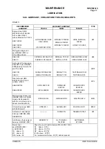
BRAKES
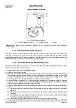
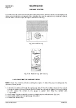
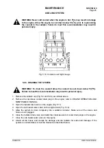
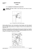
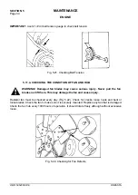
Fig. 5.7. Adding Fluid Into Master Brake Cylinder
1. Master Brake Cylinder
2. Access Door
If the sight gauge is only partially filled or shows no fluid, lift the inspection door (2, Fig. 5.7) in the
floorboard just to the left of the operator’s seat. Clean filter cap (2) before removing it to prevent
foreign matter from falling into the master cylinder housing. Undo the securing fasteners and
remove the filter cap (1, Fig. 5.7) and add fluid. The correct fluid level is 6 [mm] from the top edge of
the master cylinder. Reinstall the filler cap.
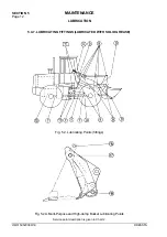
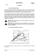
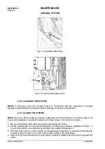
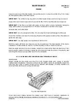
5.7.3. CHANGING THE BRAKE FLUID
Perform the following steps when changing brake fluid:
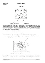
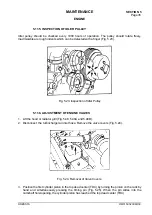
1. Disassemble brake system warning light switch (3) from differential valve (2, Fig. 6.7)
2. Disconnect brake lines (1 and 2) supplying both LH and RH brakes of both axles from tee
connector (3, Fig. 5.8). Connect the lines and drain the fluid from the drive axle to a container.
Fig. 5.8. Disconnecting Service Brake Piping
1. Supplying Tube 2. Supplying Tube
3. Tee
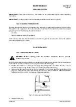
3. Pressing the brake pedal pump the brake fluid out of the circuit into the container till all the fluid
has flown out and air escapes from the circuit.
4. If necessary, (i.e. if still some fluid has remained in the master cylinder), disconnect the lines
from the master cylinder and drain the remaining fluid.
Summary of Contents for 515C
Page 3: ...OM515C520C99 1E DRESSTA ...
Page 5: ......
Page 7: ......
Page 10: ...SECTION 1 INTRODUCTION ...
Page 12: ......
Page 17: ...SECTION 2 SAFETY PRECAUTIONS ...
Page 19: ......
Page 37: ...SECTION 3 MACHINE TRANSPORT AND STORAGE ...
Page 39: ......
Page 49: ...SECTION 4 OPERATING ...
Page 51: ......
Page 107: ...SECTION 5 MAINTENANCE ...
Page 165: ...SECTION 6 SPECIFICATIONS ...
Page 167: ......
Page 181: ...SECTION 6 SPECIFICATIONS Page 16 OM515C520C99 1E DRESSTA WIRING DIAGRAMS ...
Page 182: ...SPECIFICATIONS SECTION 6 Page 17 DRESSTA OM515C520C99 1E WIRING DIAGRAMS ...
Page 187: ...SECTION 6 SPECIFICATIONS Page 22 OM515C520C99 1E DRESSTA WIRING DIAGRAMS ...