SECTION 5
MAINTENANCE
Page 18
OM515C520C99/1E
DRESSTA
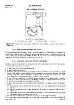
AIR CLEANING SYSTEM
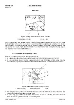
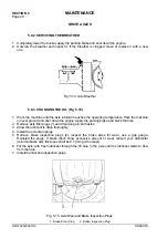
Fig. 5.5. Air Cleaning System
1. Air Cleaner Service Indicator 2. Precleaner Hood 3. Clamp
IMPORTANT:
Never wash precleaner installed on the machine as water may penetrate
to the engine.
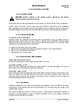
5.6.5. DUST VACUATOR VALVE (2, Fig. 5.3)
The dust vacuator will automatically remove dust and water from the air cleaner. To function, the
vacuator valve lips must point downward and be kept free of debris. The lips should be closed
except when engine is idling slowly or stopped. If the vacuator valve is lost or damaged, replace it to
maintain air cleaner efficiency and normal element service life.
5.6.6. CHECKING AIR INTAKE SYSTEM FOR LEAKS
Air intake system leakproof tests must be performed after each disassembly of the intake system
or if necessary (leaks or loose clamps).
1. Remove the cover from the air cleaner body.
2. Remove the primary element.
3. Mask the entire perforated metal outside diameter of safety element (smaller) with the duct tape
and reinstall. Sealing must be airtight. Connect regulated compressed air supply to one of the
existing connecting ports on air intake manifold. Connect the pressure gauge to the other
connecting port on the intake manifold to air cleaner service indicator.
4. Check if pressure reading of 15–30 [kPa] has been obtained on the pressure meter. If improper
pressure is seen, adjust pressure to 15–30 [kPa] by cranking the engine crankshaft to a position
where minimum leakage occurs past engine valves.
5. Coat the following areas with soap solution and check for leaks. Leaks will cause air bubbles to
form.
a) the air cleaner body surface around the outlet pipe to app. the outside diameter of the safety
element,
B) the pipe connector and the hose between the air cleaner outlet and air cleaner service
indicator,
C) all clamped hose and gasket connections between the air cleaner outlet and the intake
manifold including turbocharger connections,
D) the surface of all air induction hoses, the air cleaner and air intake manifold,
6. No leakage is permitted between air cleaner and intake manifold (the entire air induction
Summary of Contents for 515C
Page 3: ...OM515C520C99 1E DRESSTA ...
Page 5: ......
Page 7: ......
Page 10: ...SECTION 1 INTRODUCTION ...
Page 12: ......
Page 17: ...SECTION 2 SAFETY PRECAUTIONS ...
Page 19: ......
Page 37: ...SECTION 3 MACHINE TRANSPORT AND STORAGE ...
Page 39: ......
Page 49: ...SECTION 4 OPERATING ...
Page 51: ......
Page 107: ...SECTION 5 MAINTENANCE ...
Page 165: ...SECTION 6 SPECIFICATIONS ...
Page 167: ......
Page 181: ...SECTION 6 SPECIFICATIONS Page 16 OM515C520C99 1E DRESSTA WIRING DIAGRAMS ...
Page 182: ...SPECIFICATIONS SECTION 6 Page 17 DRESSTA OM515C520C99 1E WIRING DIAGRAMS ...
Page 187: ...SECTION 6 SPECIFICATIONS Page 22 OM515C520C99 1E DRESSTA WIRING DIAGRAMS ...

