SECTION 6
SPECIFICATIONS
Page 4
OM515C520C99/1E
DRESSTA
TECHNICAL DESCRIPTION
CAB
A cab includes ROPS-FOPS protecting structure providing the operator protection against injury
under weight of the machine in the event of machine rollover or upset. Also, the structure provides
protection against falling objects. The cab meets safety requirements of SAE standard 1040C.
LOADER EQUIPMENT
The Z-type loader linkage system provides significant dump angle within the whole operating range
of the loader linkage system. It features excellent capacity, breakout force and resistance to
dynamic loads ensuring high operational durability and reliability.
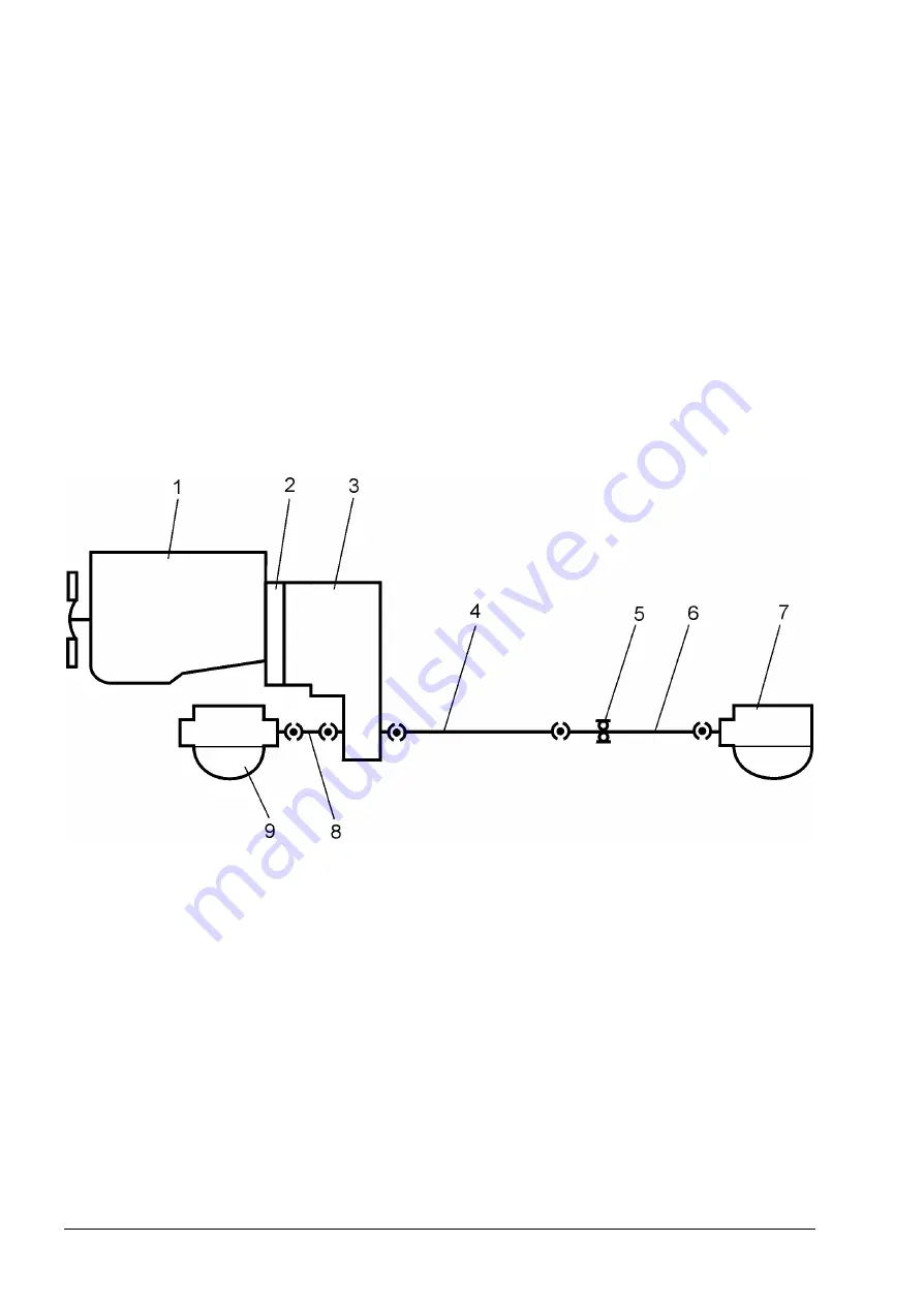
6.3. SCHEMATIC OF 515C AND 520C WHEEL LOADERS DRIVE TRAIN
Fig. 6.1. 515C and 520C Wheel Loaders Drive Train Schematic
1. Engine
2. Torque Converter
3. Transmission
4-6-8. Drive Shafts
5. Transfer Drive
7. Front Drive Axle
9. Rear Drive Axle
Summary of Contents for 515C
Page 3: ...OM515C520C99 1E DRESSTA ...
Page 5: ......
Page 7: ......
Page 10: ...SECTION 1 INTRODUCTION ...
Page 12: ......
Page 17: ...SECTION 2 SAFETY PRECAUTIONS ...
Page 19: ......
Page 37: ...SECTION 3 MACHINE TRANSPORT AND STORAGE ...
Page 39: ......
Page 49: ...SECTION 4 OPERATING ...
Page 51: ......
Page 107: ...SECTION 5 MAINTENANCE ...
Page 165: ...SECTION 6 SPECIFICATIONS ...
Page 167: ......
Page 181: ...SECTION 6 SPECIFICATIONS Page 16 OM515C520C99 1E DRESSTA WIRING DIAGRAMS ...
Page 182: ...SPECIFICATIONS SECTION 6 Page 17 DRESSTA OM515C520C99 1E WIRING DIAGRAMS ...
Page 187: ...SECTION 6 SPECIFICATIONS Page 22 OM515C520C99 1E DRESSTA WIRING DIAGRAMS ...


