background image

SECTION 6

SPECIFICATIONS

Page 22

OM515C520C99/1E 

DRESSTA

WIRING DIAGRAMS

Summary of Contents for 515C

Page 1: ...OPERATOR S MANUAL 515C 520C SERIAL NUMBER 7001 AND UP 9001 AND UP FOR 515CH SERIAL NUMBER 11001 AND UP 13001 AND UP FOR 520CH DRESSTA Co Ltd A JOINT VENTURE OF KOMATSU AMERICA INTERNATIONAL CO AND HUTA STALOWA WOLA S A ...

Page 2: ...ncy and safety Read this manual thoroughly and learn your machine before you attempt to operate it It is our policy to improve our products whenever it is possible and practical to do so We reserve the right to make changes or add improvements at any time without incurring any obligation to install such changes on products sold previously Due to this continuous program of research and development ...

Page 3: ...OM515C520C99 1E DRESSTA ...

Page 4: ...TA OM515C520C99 1E SECTION INDEX Section 1 Introduction 1 1 Section 2 Safety Precautions 2 1 Section 3 Storage and Shipping 3 1 Section 4 Operating 4 1 Section 5 Maintenance 5 1 Section 6 Specifications 6 1 ...

Page 5: ......

Page 6: ...emaining portion of this section outlines and illustrates the step by step procedures for starting operating and stopping the machine and discusses a few operating suggestions and techniques and simple ideas to help ease the work and lengthen the useful life of your machine SECTION 5 MAINTENANCE The beginning of this section outlines a complete scheduled maintenance program which helps to reduce d...

Page 7: ......

Page 8: ...al 3 4 2 Universal Symbols for Instruments and Controls 4 4 3 Instruments and Controls 8 4 4 Cab Door and Windows 20 4 5 Operator s Seat 21 4 6 Seat Belt 24 4 7 Cab Heating and Ventilation 25 4 8 Air Cleaner Service Indicator 27 4 9 Electrical Master Switch 27 4 10 Dome Lights with Switches 28 4 11 Starting and Stopping the Engine 28 4 12 Driving the Machine 30 4 13 Shifting Gears 32 4 14 Steering...

Page 9: ...r Heater 56 6 SPECIFICATIONS 6 1 Application 3 6 2 Technical Description 3 6 3 Schematic of 515C and 520C Wheel Loader Drive Train 4 6 4 Schematic of Transmission Hydraulic System 5 6 5 Loader Equipment and Steering Hydraulic System Schematic 6 6 6 Wiring Diagram 14 6 7 Brake Hydraulic System Schematic 25 6 8 Specifications 26 6 9 515C and 520C Loader Equipment 32 6 10 Torque Values for Standard M...

Page 10: ...SECTION 1 INTRODUCTION ...

Page 11: ...INTRODUCTION SECTION 1 DRESSTA OM515C520C99 1E SECTION CONTENTS 1 1 Introduction 3 1 2 Serial Numbers 5 ...

Page 12: ......

Page 13: ... 515 Series C Wheel Loader a Right Hand Side of the Machine b Left Hand Side of the Machine c Front of the Machine d Rear of the Machine Fig 1 2 520 Series C Wheel Loader a Right Hand Side of the Machine b Left Hand Side of the Machine c Front of the Machine d Rear of the Machine ...

Page 14: ... steering and a hydraulic system controlled with either 2 or 3 levers mechanically connected with a 2 or 3 spool control valve respectively 2 upgraded version equipped with a hydraulic feedback steering and a hydraulic system controlled with 1 or 2 levers hydraulically connected with a 2 or 3 spool control valve respectively In this version it can be configured as CE version according to EC direct...

Page 15: ...3 Location of Machine Serial Number plates 1 The machine serial number plate is located at the bottom of the left hand side of the cab It is also stamped on the left rear corner of the rear frame Fig 1 4 Location of stamped machine serial number Fig 1 5 Engine Serial Number Plate ...

Page 16: ...g 1 6 Cab Serial Number Plate 3 The cab serial number plate is located inside the cab in the right front corner near the floor board Fig 1 6 All other main components having serial numbers are each equipped with a separate serial number plate or the number is stamped on the component body Use respective serial numbers when requesting information or ordering parts and proper numbers from Parts Cata...

Page 17: ...SECTION 2 SAFETY PRECAUTIONS ...

Page 18: ...99 1E SECTION CONTENTS 2 1 General 3 2 2 Before Starting the Engine 4 2 3 Operating the Machine 4 2 4 General Maintenance Precautions 6 2 5 When Parking 10 2 6 Safety Graphics Location 11 2 6 1 Safety Graphics 12 2 6 2 Safety Graphics Version CE 16 ...

Page 19: ......

Page 20: ...he machine must be equipped with a safety triangle If the machine is equipped with outside ventilation check the engine exhaust system periodically for leaks Exhaust gases are dangerous to the operator On machines equipped with a cab without outside ventilation keep sliding windows open to outside air The operator must not wear loose fitting or hanging clothing belts or jewelry and must wear shoes...

Page 21: ...erating the machine check that the frame locking bar and pin are stowed on the rear frame Broken or lost frame locking bar and pin should be repaired or replaced immediately so that this device is always available for use When using a booster battery and jumper cables switch off the master switch then connect the positive terminal on the booster battery to the positive terminal of the battery on t...

Page 22: ...cks or away from the truck and loader If the machine begins to tip over because of an overload immediately lower the bucket to regain stability Do not swing a load over the heads of other workers or a truck cab A machine s weight and the vibration it creates can cause the edge of a high wall to collapse Keep your machine back from the edges of banks and excavations If this cannot be avoided face t...

Page 23: ...into neutral N The machine could go out of control or the power train could be damaged when the pedal is released and the transmission is shifted into gear again Do not drive the machine without checking the brakes for correct operation Avoid sidehill travel whenever possible Drive straight up and down the hill If the machine starts slipping sideways turn downhill immediately and lower the bucket ...

Page 24: ...tions and equipment should be used Never attempt to start servicing close to the operating fan as it may result in serious injury When changing cutting edges securely support the bucket for your protection If the bucket is provided with teeth use special hammer for installation to prevent teeth breakage Wear safety goggles Lift and handle all heavy parts with lifting devices of adequate capacity S...

Page 25: ...ed in neutral N the parking brake is applied and the frame halves are locked together Never stand near the bucket or tires while the engine is running If compressed air or water under pressure is used for cleaning parts wear safety goggles Limit air pressure to 200 kPa and water pressure to 270 kPa Never run the engine when cleaning or lubricating the machine because serious injury could result fr...

Page 26: ...aken the structure or affect the overall energy absorption capability Always wear the seat belt during all operation in order to realize protection of the ROPS or cab When transporting the machine lock the frame halves together with the frame locking bar and pins Corrosion inhibitors are volatile and flammable Use them only in a well ventilated area Keep flames and sparks away Do not smoke Store c...

Page 27: ...her and storm lightning is nearby dismount and seek shelter away from the machine Lightning will be attracted to the machine and cause serious injury or death ADDITIONAL INFORMATION 1 The vibration level measured at the operator s seat does not exceed the admissible value of 1 25 m s2 according to PN 91 N 01352 standard 2 The noise level measured at the operator s seat during intensive operation d...

Page 28: ...SAFETY PRECAUTIONS SECTION 2 Page 11 DRESSTA OM515C520C99 1E 2 6 SAFETY GRAPHICS LOCATION Fig 2 1 Safety Graphics Location ...

Page 29: ...SSTA SAFETY GRAPHICS LOCATION 2 6 1 SAFETY GRAPHICS Decal 1 On the rear frame near the center articulation pivot and on the instrument panel in the operator s cab Decal 2 On the rear frame near the center articulation pivot Decal 3 Near the ladders and steps ...

Page 30: ...SAFETY PRECAUTIONS SECTION 2 Page 13 DRESSTA OM515C520C99 1E SAFETY GRAPHICS LOCATION Decal 4 Near the radiator filler cap Decal 5 On the hydraulic reservoir Decal 6 In the operator s cab ...

Page 31: ...ON 2 SAFETY PRECAUTIONS Page 14 OM515C520C99 1E DRESSTA SAFETY GRAPHICS LOCATION Decal 7 In the operator s cab Decal 8 In the cab on the side window Decal 9 In the operator s cab Decal 10 On the battery box ...

Page 32: ...SAFETY PRECAUTIONS SECTION 2 Page 15 DRESSTA OM515C520C99 1E SAFETY GRAPHICS LOCATION Decal 11 On the battery box ...

Page 33: ...AFETY GRAPHICS LOCATION 2 6 2 SAFETY GRAPHICS Version CE Decal 1 On the rear frame near the center articulation pivot and on the instrument panel in the operator s cab Decal 2 On the rear frame near the center articulation pivot Decal 3 Near the ladders and steps ...

Page 34: ...SAFETY PRECAUTIONS SECTION 2 Page 17 DRESSTA OM515C520C99 1E SAFETY GRAPHICS LOCATION Decal 4 Near the radiator filler cap Decal 5 On the hydraulic reservoir Decal 6 In the operator s cab ...

Page 35: ...ON 2 SAFETY PRECAUTIONS Page 18 OM515C520C99 1E DRESSTA SAFETY GRAPHICS LOCATION Decal 7 In the operator s cab Decal 8 In the cab on the side window Decal 9 In the operator s cab Decal 10 On the battery box ...

Page 36: ...SAFETY PRECAUTIONS SECTION 2 Page 19 DRESSTA OM515C520C99 1E SAFETY GRAPHICS LOCATION Decal 11 On the battery box ...

Page 37: ...SECTION 3 MACHINE TRANSPORT AND STORAGE ...

Page 38: ...3 3 1 1 General 3 3 1 2 Transportation on Trailer Railway Car or by Sea 5 3 1 3 Transportation by Machine Own Drive 5 3 2 Lifting on Slings 5 3 3 Moving a Disabled Machine 6 3 4 Machine Storage 7 3 4 1 Preparing for Storage 7 3 4 2 Servicing During Storage 9 3 4 3 Preparing for Operation after Storage 10 ...

Page 39: ......

Page 40: ...nd rear frame of a loader to prevent accidental frame turning during service and lifting on lifting slings METHOD OF LOCKING OF FRONT AND REAR FRAME OF LOADER Prior to operating of the machine place the locking bar in the stowed position as shown in Fig 3 1 Repair or replace the frame locking bar and pins if damaged or lost to ensure frame locking Fig 3 2 Fig 3 1 Frame Locking Bar and Pins in stow...

Page 41: ...uel 4 The parking brake should be applied The pressure in the tires should conform to this instruction see TIRES Section 6 5 The batteries should be fully charged the electric system master switch turned off 6 The starting switch should be in the neutral position and the key removed IMPORTANT When transporting this machine on a high speed carrier or railaway car seal the exhaust pipe and air intak...

Page 42: ...e machine The lifting slings used for fastening the loader should be attached only to special lifting lugs marked with special plates on the machine Fig 3 4 3 1 3 TRANSPORTATION BY MACHINE OWN DRIVE 1 Passage conditions must be coordinated with the local road traffic administration 2 Observe the traffic regulations ensuring a safe travel 3 Do not drive a loader at long distances 4 Place the boom a...

Page 43: ...e turning and braking of the machine Towing of machines equipped with ground driven system is easier Prior to towing release spring parking brake refer to PARKING BRAKE Section 5 and unlock frames by placing locking bar in the stowed position as shown in Fig 3 1 and 3 1A WARNING When pulling with a chain or cable take up the slack slowly to avoid jerking A chain or cable which fails under load can...

Page 44: ... operations 1 Visually inspect the machine for external leakage and other defects 2 Clean the radiator refer to CLEANING THE RADIATOR Section 5 3 Thoroughly clean the machine be sure to rinse off any caustic residue 4 Correct any defects found Consult Authorized Distributor of Construction Equipment 5 Clean or replace the air cleaner filter elements Refer to AIR CLEANING SYSTEM Section 5 6 The coo...

Page 45: ...pacity VCI may be purchased from NOX RUST VCI 105 OIL DAUBERT CHEMICAL COMPANY 1200 JORIES BLVD OAK BROOK ILLINOIS 60521 USA or Machine Distributor 11 Deaerate the fuel system Refer to FUEL SYSTEM Section 5 12 Start the engine and run idle at half throttle for 3 minutes and then stop the engine 13 Lubricate all points of the machine as outlined in the SERVICE GUIDE Section 5 IMPORTANT Be sure to o...

Page 46: ... solvent vapors WARNING Use extra caution when jacking up the machine Jacking up the machine can be hazardous if performed improperly Use jacking equipment of sufficient capacity Be sure the jacking points are strong enough to support the machine Be sure the jack is stable and well supported Before jacking up the machine block the tires which will not be lifted Lock the frame halves together with ...

Page 47: ... necessary 5 If the machine was jacked up refer to 3 4 1 item 24 inflate the tires to the normal operating inflation pressure Refer to TIRES Section 6 6 Remove all seals from the machine filler plugs breathers engine air intake and exhaust etc 7 Remove the air cleaner filter elements for cleaning or replacement Refer to AIR CLEANING SYSTEM Section 5 8 Remove and replace the fuel filters Refer to C...

Page 48: ...nless proper exhaust ventilation is provided Once the engine is running move the machine outdoors as soon as possible Exhaust gases are dangerous and can cause unconsciousness and death 13 Start the engine refer to STARTING AND STOPPING THE ENGINE Section 4 and SCHEDULED MAINTENANCE GUIDE recommendations daily service Section 5 ...

Page 49: ...SECTION 4 OPERATING ...

Page 50: ... the Engine 30 4 12 Driving the Machine 30 4 13 Shifting the Gears 32 4 14 Steering 32 4 15 Stopping the Machine 33 4 16 Parking the Machine 34 4 17 Loader Operations 34 4 17 1 Boom Control Lever Positions 34 4 17 2 Automatic Boom Kick Out 36 4 17 3 Bucket Control Lever Positions 37 4 17 4 Automatic Bucket Leveler 38 4 17 5 Multi purpose Bucket Control Lever Positions if equipped 38 4 18 Loader Te...

Page 51: ......

Page 52: ...ry repairs or adjustments before operating the machine Do not place a machine under load without the proper engine oil pressure and operating temperature After starting the engine move the accelerator pedal to the low idle position Allow the engine to run at low idle for 3 to 5 minutes at 1000 RPM until normal oil pressure registers on the gauge to obtain complete distribution of the lubricating o...

Page 53: ...uments and controls These symbols are an effort to overcome language differences for all operators in a positive way thus enhancing their safety through quicker recognition of the instruments and controls while operating the equipment Study the following symbols so you will know their meaning immediately and at a glance NOTE Some symbols may not pertain to your machine ...

Page 54: ...OPERATING SECTION 4 Page 5 DRESSTA OM515C520C99 1E UNIVERSAL SYMBOLS FOR INSTRUMENTS AND CONTROLS Fig 4 1 Universal Symbols for Instruments and Controls ...

Page 55: ...SECTION 4 OPERATING Page 6 OM515C520C99 1E DRESSTA UNIVERSAL SYMBOLS FOR INSTRUMENTS AND CONTROLS ...

Page 56: ...gine Oil Fill 25 Engine Oil Level 26 Engine Oil Pressure 27 Engine Oil Temperature 28 Engine Oil Filter 29 Engine Starting Aid 30 Fuel Fill 31 Fuel Level 32 Fuel Reserve 33 Fuel Filter 34 Air Pressure 35 Air Filter 36 Coolant Fill 37 Coolant Level 38 Coolant Pressure 39 Coolant Temperature 40 Power Train Oil Fill 41 Power Train Oil Level 42 Power Train Oil Pressure 43 Power Train Oil Temperature 4...

Page 57: ...i Purpose Bucket Roll Back 83 Multi Purpose Bucket Hold 84 Multi Purpose Bucket Dump 85 Grapple Closing 86 Grapple Hold 87 Grapple Opening 88 Boom With Bucket Raise 89 Boom With Bucket Hold 90 Boom With Bucket Lower 91 Boom With Bucket Float 92 Bucket Roll Back 93 Bucket Dump 94 Ground Driven System 95 Change of Direction Forward Reverse 96 RSM Ride Control 97 Quick Coupler Connected 98 Quick Coup...

Page 58: ... Engine Oil Pressure Warning Light 3 Engine Coolant Temperature Warning Light 4 Parking Brake Warning Light 5 Engine Coolant Temperature Gauge 6 Fuel Level Gauge 6A Turn Signal Warning Light 6B Engine Oil Pressure Gauge 7 Ether Start Button 8 Instrument Panel Illumination Light 9 Starting Switch 10 Rear Parking and Front Work Lights Switch Front Rear Parking Lights Low Beam Lights Switch in CE Ver...

Page 59: ...t If the light comes on maneuver the machine to the side and operate the engine at low idle Do not shut the engine down If the light stays on investigate the cause and take corrective action before operating the machine again 4 PARKING BRAKE WARNING LIGHT The light will indicate if the parking brake is applied At the same time a buzzer will sound IMPORTANT Release the parking brake before moving a...

Page 60: ...ove 0 C Follow the correct method for starting the engine 8 INSTRUMENT PANEL ILLUMINATION LIGHT The light illuminates the lower part of the instrument panel with the starting switch when the parking lights are on 9 STARTING SWITCH Fig 4 3 Starting Switch Positions The starting switch is used to connect and disconnect the circuits of the electric system and switching on and off the engine and is eq...

Page 61: ...NDOW HEATING SWITCH It switches on and off the rear window heating 13C FLASHLIGHT SWITCH It switches on and off the flashlight mounted on the cab roof 14 VOLTMETER The voltmeter indicates the condition of the batteries At low idle speed the gauge pointer should be within the first green area which indicates a good battery charge If the voltage drops below the first green area the batteries should ...

Page 62: ... and must be replaced c air cleaner warning light it comes on when the cleaner elements are contaminated and must be washed or replaced d low engine coolant warning light it comes on when the coolant in the radiator top tank reaches its minimal level e hydraulic oil temperature warning light it comes on when the oil temperature is too high 20 24V RECEPTACLE Used for connecting portable lamp with c...

Page 63: ...ver 24 Transmission Direction Lever 25 Turn Signal and Emergency Light Switch 26 Boom Control Lever 27 Bucket Control Lever 28 Auxiliary Equipment Lever 29 Accelerator Pedal 30 Steering Wheel 31 Horn Button 32 Brake Pedal 33 Brake and Transmission Disconnect Pedal 34 Hydraulic Pilot Control Valve Lock Switch 35 Control Levers Lock Plate Fig 4 7 36 Float Position Lock Switch 37 Bucket and Boom Pilo...

Page 64: ...h turn signal lights flash at the same time in CE version the emergency lights and the turn signal warning lights are located on the instrument panel see item 6A 14B 26 BOOM CONTROL LEVER The lever controls raising and lowering operations of the boom Refer to Par 4 17 1 for additional information 27 BUCKET CONTROL LEVER The lever controls roll back and dumping operation of the bucket Refer to Par ...

Page 65: ...to extend the steering column Push it down to change the inclination Fig 4 6 Steering Column Adjustment Upgraded Machine 1 Lever 31 HORN BUTTON Depress the button to sound the horn release the button to stop 32 BRAKE PEDAL This pedal actuates the machine service brakes Depress the pedal gradually increasing pressure until a desired braking action is achieved The faster pressure is applied to the p...

Page 66: ...in the neutral position and guard them against accidental activation In the illustration above the plate is shown in the non locked position To lock it turn the plate round 180 WARNING When roading the machine engage the hydraulic control lever locking plate Accidental actuation of the levers may cause personal injury or damage of the machine 36 FLOAT POSITION PILOT VALVE LOCK SWITCH This switch h...

Page 67: ...ating air inside the cab It has three positions OFF LO HI Move the switch to the desired position If the air outside is very dusty switch the fan into HI position This will create high pressure inside the cab which will prevent dusty air from coming into the cab 39 HEATER AIR CONDITIONING TEMPERATURE CONTROL If lower temperature is required turn the knob to the left If higher temperature is requir...

Page 68: ...EQUIPPED This switch controls the rear window washers Push the switch button down to run the washer Release the button to stop the washer Use the washer prior to switching on the wipers to protect the windshield from being scratched 46 PARKING BRAKE LEVER Fig 4 10 The parking brake lever is located to the rear right of the operator s seat on the floorboard To apply the parking brake pull the lever...

Page 69: ...the windows slide the window up or down as required and put latch 1 in the catch WARNING Do not operate the machine with left hand cab door opened Fig 4 11 Left Hand Cab Door 1 Window Latch 2 Door Handle CAB DOOR LATCH Fig 4 11A CE VERSION Fig 4 11A Cab Door Latch The cab door may be locked in an open position The latch is particularly useful for cab ventilation when operating in high ambient temp...

Page 70: ...he seat position while the machine is moving because a lose of control may result Stop the machine apply the parking brake and then adjust the seat position SOLID BASE OPERATOR S SEAT Fig 4 13 For operator s convenience in reaching the controls and improved operating visibility the operator s seat can be adjusted to various positions The seat adjustment lever is attached to the bottom left front s...

Page 71: ... reaching the controls and improved operating visibility the operator s seat can be adjusted to various positions Pull lever 4 back and slide the seat to the desired forward or rearward position Release the lever to lock the seat To adjust the angle of the back seat cushion lift up the seat back and tilt it to one of its three positions Release the cushion allowing the catches on the seat back to ...

Page 72: ...eat travel adjustment pull up the lever 3 on the right hand side of the seat and slide the seat forward or rearward to the desired position and lock with the lock lever Seat height adjustment lift the seat cushion up or press it down and hold it with both hands until it settles at the desired height Backrest angle adjustment pull up lever 7 to release the lock Upon the adjustment of the backrest a...

Page 73: ...Fasten the belt and remove it in the following manner 1 Adjust the seat so that the brake pedal can be depressed all the way with the operator s back against the backrest 2 With the seat unoccupied tense belt 1 lightly across the seat and install Check that there are no kinks in the belt 3 Sit in the seat Hold buckle 2 and insert tang 3 into the buckle Check that the bet has locked by pulling it 4...

Page 74: ...efrosting or defogging the windshield The switch has two positions and is located on the side control panel 43 Fig 4 19 WARNING Turn off the motor before adjusting defroster fan to avoid hand injury 4 7 2 HEATER For cab heating ventilation and air conditioning integrated heater and air conditioner installed in the right hand side of the cab wall is used The heater and air conditioner controls are ...

Page 75: ... The wheel loader may be equipped with air conditioner to reduce air temperature and relative humidity inside the cab An air conditioner consists of the following principal components 1 Compressor V belt driven thru pulley mounted on the engine 2 Condenser radiator mounted 3 Dehumidifier mounted on a bracket on the RH side of the rear frame 4 Evaporator RH side cab wall mounted 5 Expansion valve i...

Page 76: ...e is required Press the reset button on top of indicator after the elements have been serviced 4 9 ELECTRIC SYSTEM MASTER SWITCH Fig 4 22 Electric System Master Switch Fig 4 22A Electric System Master Switch CE Version The switch is located on the LH side of the hydraulic tank behind the cab and is connected in series between the battery positive terminal and receivers thus turning ON or OFF batte...

Page 77: ...l position 3 Turn the master electric system switch ON Refer to Fig 4 22 4 22 A 4 With your back against the back rest of the operator s seat adjust the seat position so that the brake and decelerator pedal can be easily depressed Refer to Fig 4 6 5 Sound the horn to clear the area of personnel NOTE All the warning lights should light up while the starting key is between RUN and START position Rep...

Page 78: ...ut off valve electric wire and crank the engine until oil pressure registers on the gauge and the oil pressure warning light goes out Connect the fuel shut off valve wire again Start the engine as described above 4 11 2 COLD WEATHER START USING ETHER INJECTOR AMBIENT TEMPERATURE BELOW 0 C NOTE Never operate ether injector switch except when starting the engine WARNING Ether starting fluid is highl...

Page 79: ...y 9 Check all the instruments for proper operation 4 11 3 STOPPING THE ENGINE 1 Allow the engine to cool down after operation at full load Run the engine with no load at idle for about 3 to 5 minutes before shutting it down to ensure a gradual and even cooling IMPORTANT Failure to do so may result in damage to the engine and turbocharger 2 Shut down the engine by turning the starting key to the OF...

Page 80: ...e parking brake lever 6 3 Using lever 8 standard version or lever 5 upgraded version raise the boom until the bucket is off the ground and in the carry position 4 Using lever 7 standard version or lever 5 for upgraded version close the bucket 5 Place transmission gear range lever 1 in the first gear position 6 Move the transmission hinge lock plate to the right Then place the transmission directio...

Page 81: ... intend to shift down to Failure to do so results in sudden braking of the machine For speed ranges in the respective gears refer to TRANSMISSION Section 6 IMPORTANT Down shifting from 3 to 1 or 2 when driving at maximum speed may result in drive train damage UP SHIFTING An up shift from 1 to 2 or from 2 to 3 can be made at any speed To get proper acceleration speed up the machine to the maximal s...

Page 82: ... exerted on the brake pedal the higher pressure the more efficient braking WARNING Never brake with the drive disconnected 33 Fig 4 4 or 4 5 when traveling fast or going downhill Releasing the brake pedal automatically makes the transmission clutches to re engage With ground speed higher than the maximal speed at the previously shifted gear the machine will brake suddenly which may result in a los...

Page 83: ...tires as shown in Fig 4 27 NOTE Avoid parking the machine in puddles of oil grease or gasoline because this damages the tires Fig 4 27 Hillside Parking NOTE Park the machine on level ground to obtain accurate coolant lubricant hydraulic fuel level checks 4 17 LOADER OPERATIONS The loader equipment is hydraulically operated When the bucket circuit is being operated oil flow to the boom is cut off I...

Page 84: ...HOLD must be done manually or will be done automatically when the boom reaches the preset stopping height of the automatic boom kick out HOLD B Fig 4 28 4 29 The control lever when not in a detented position will automatically return to HOLD when released The boom will remain stationary in this position LOWER C Fig 4 28 4 29 Push the lever part way forward in standard version or all the way forwar...

Page 85: ...c field circuit which is completed by the proximity of adjustment plate 2 within the magnetic field Once the boom is raised to its preselected height adjustment plate 2 has moved out of the magnetic field breaking the circuit Breaking the magnetic field circuit causes the boom control lever to move out of the detented RAISE position and into the HOLD position thereby stopping the travel of the boo...

Page 86: ...imit of its travel will produce excessive heat in the hydraulic system which may affect loader performance ROLL BACK E Fig 4 29 and 4 31 To roll the bucket back load the bucket pull the lever a in standard version all the way back b in upgraded version to the left towards the operator When the automatic leveler is inoperative the lever automatically returns to the hold position when released When ...

Page 87: ...C BOOM KICK OUT Place the bucket flat on the ground Place the key in the starting switch in the RUN position If the electromagnetic field of proximity switch 2 is making contact with trip bar 1 mounted under the cylinder rod the bucket control lever will stay in the HOLD position Slide the proximity switch mounting U bolt back toward the base end of cylinder until contact of the electro magnetic f...

Page 88: ... to what extent the clam is opened or closed 0 indicates closed 2 indicated half open and 4 indicates a fully open clam To set the multi purpose bucket as a bucket pull the control lever back until the clam indicator is at the 0 setting on the clam product graphic A Fig 4 33 Fig 4 33 Multi purpose Bucket set in Bucket Position A Clam Product Graphic To set the multi purpose bucket as a scraper ope...

Page 89: ... the clam indicator is at the bottom of the clam decal A Fig 4 35 Fig 4 35 Multi purpose Bucket set in Dozer Position A Clam Product Graphic Position A Fig 4 36 is for level grading Position B Fig 4 36 is for a deeper cut and position C Fig 4 36 is for a lesser amount of cut Fig 4 36 Dozer Blade Pitch Position A Clam Product Graphic ...

Page 90: ...usive Each work situation will vary Loader operation may be altered for each particular application for its best efficiency When possible start all jobs from relatively level ground If necessary level an area large enough to provide sufficient working space This prevents back and forth pitching of the loader and will result in easier operation Avoid wheel spin whenever possible this wastes effort ...

Page 91: ...ction will loosen the material and improve bucket loading Coordinated operation of the two hydraulic control levers as the bucket enters the material will yield satisfactory bucket loads The boom assy need not be fully raised to dump the bucket Adjust the dump height to the height of the side of the loaded vehicle NOTE The boom assembly need not be fully raised to load the bucket Maximum bucket lo...

Page 92: ...til the indicator points to 2 or 4 on the clam product graphic A Fig 4 42 according to the desired depth of cut Fig 4 42 Multi purpose Bucket set in Scraper Position A Clam Product Graphic 3 To use a multi purpose bucket as a bucket roll the bucket forward or backward and move the machine forth The cutting edge will penetrate into the ground till the clam s cutting edge gets into full contact with...

Page 93: ...cylinders and linkage 5 When stockpiling move each load only once and keep travel distance down to a minimum When possible locate stockpiles as close as possible without hindering other work on the site WRONG RIGHT Fig 4 46 Bank Loading 6 Transport filled bucket in the roll back position close to the ground Fig 4 47 If it is necessary to carry the bucket raised in transit the operator should use i...

Page 94: ... the bucket and raise the boom to loosen dirt from within When the bucket empties close it Back the loader away from the truck lower the boom and return to the loading site If the boom height is insufficient to clear the truck pack or the loaded container build a ramp out of hard ground Using the automatic boom kick out and bucket leveler is particularly recommended in continuous operation of even...

Page 95: ...into the center of the truck from the lowest possible height Fig 4 50 Dumping Large Rocks Into Truck Plan excavating jobs so that most of the work can be done with the loader being driven forward rather than being backed out Use as flat a ramp as possible A steeper ramp can be used when driving forward rather than in reverse Always feed the bucket into the ground gradually until the desired depth ...

Page 96: ...d to the desired dump area Fig 4 51 Digging or Excavating Clearing an excavation Fig 4 52 may be performed with the bucket partly in the dump position by disposing of the material carried in the bucket It is recommended to clear an excavation a little above the ground level because after compaction the ground will be level Approach an excavation at the right angle and stop the front wheels at a sa...

Page 97: ...53 Fig 4 53 Bank Loading 1 With the clam fully open the multi purpose bucket can be used as a bulldozer Position the bucket as shown in Fig 4 54 for digging When the ground is hard or frozen and the area must be ripped before it can be worked rip a relatively small section and work it to grade before enlarging the cut This will require ripping each section only once not every morning after the gro...

Page 98: ...th the top of the bucket Fig 4 55 WARNING When using the machine for site clearing and tree removal protect the operator from trees and branches Fig 4 55 Position of the Bucket When Removing Small Tree A Wrong B Right Heavy roots of large trees may require cutting from several sides of the tree Fig 4 56 Use a cable to topple and remove trees from soft ground Topple the tree back the loader and low...

Page 99: ... under the rock with the bucket Fig 4 57 Lifting the rock with the bucket while pushing will increase traction i reduce wheel spinning Never use the clamshell to remove buried or anchored objects Fig 4 57 Large Rock Removal When finishing a non solid material position the bucket as shown in Fig 4 58 or Fig 4 59 and backdrag the loose material This method is not recommended where abrasive material ...

Page 100: ...ldoze material Position the bucket as shown in Fig 4 61 for level grading Position the bucket as shown in Fig 4 62 for spreading or to obtain a lesser cut Fig 4 61 Leveling with Multi Purpose Bucket Fig 4 62 Bulldozing with Multi Purpose Bucket 6 Improper use of the multi purpose bucket Much unnecessary damage can be done to multi purpose buckets by subjecting them to uses for which they were not ...

Page 101: ...r anchored objects with the clam while backdragging it may bend the clam Fig 4 64 DO NOT side load the clam against anchored objects especially when open Fig 4 65 This may bend the sides of the clam Wrong Wrong Fig 4 65 Side Loading the Clam against an Anchored Object Fig 4 66 Uneven Stress to Clam DO NOT clamp objects on only one side of the clam It causes uneven stresses and may twist the clam o...

Page 102: ...Bucket DO NOT grade in the forward direction with the bucket in dump position Fig 4 68 This could cause damage to tilt cylinder and linkage Wrong Wrong Fig 4 69 Twisting the Multi Purpose Bucket out of Alignment Fig 4 70 Using Multi Purpose Bucket as Pile Driver Do not charge a bank with an object caught between the clam and blade Fig 4 69 This can twist the clam out of alignment DO NOT use the bo...

Page 103: ... bucket correctly during operation use 1 st and 2nd gear avoid maximum speed of the engine avoid stopping machine due to stall of the engine 4 20 QUICKCOUPLING The quickcoupling is a device installed on the boom designed for quick fastening and removal of the mounted equipment such as a bucket grapple forklift dozer blade etc The quickcoupling is an angle section frame fitted with an equipment bra...

Page 104: ... To secure the equipment on the tool carrier the pins in the locked position push the lever away from the operator s seat When released the lever will automatically return to the hold position The pins will remain in the locking position 4 PIN UNLOCKING To dismount the equipment mounted on the tool carrier the removal of the pins pull the lever back towards the operator s seat When released the le...

Page 105: ...HE EQUIPMENT Refer to Par 5 section 4 20 1 6 REMOVAL OF THE EQUIPMENT Refer to Par 6 section 4 20 1 4 21 RIDE STABILIZING MECHANISM Ride stabilizing mechanism is a hydraulic system consisting of a block of hydraulic valves and accumulators preset for a pressure of 1 6 MPa 16 bars there are 5 accumulators in 515C and 6 in 520C loader All the components are built in in the loader s front frame When ...

Page 106: ...To keep the rules of work safety and proper machine use to protect its excessive wear and the wear of the hydraulic system do not use the high dump bucket in the soil whose specific gravity is greater than 1300 kg m3 Working in soils exceeding this gravity particularly when the bucket is full can damage the hydraulic system or cause the loss of stability and machine tipping over 4 22 1 HIGH DUMP B...

Page 107: ...SECTION 5 MAINTENANCE ...

Page 108: ...n 17 5 6 5 Dust Vacuator Valve 18 5 6 6 Checking Air Intake System for Leaks 18 5 7 Brakes 19 5 7 1 Service Brake System 19 5 7 2 Checking the Brake Fluid Level 19 5 7 3 Changing the Brake Fluid 20 5 7 4 Filling and Venting the System 21 5 7 5 Parking Brake 21 5 8 Cooling System 22 5 8 1 Water 22 5 8 2 Antifreeze 23 5 8 3 Radiator Cap 23 5 8 4 Checking the Coolant Level 24 5 8 5 Draining the Syste...

Page 109: ... System Oil 44 5 14 3 Changing the Hydraulic Oil Return Filter 45 5 14 4 Servicing the Hydraulic Reservoir Breather 46 5 15 Seat Belt 47 5 16 Steering Gear 47 5 17 Tires and Rims 47 5 18 Transmission System 48 5 18 1 Checking the Oil Level 48 5 18 2 Changing the Oil 49 5 18 3 Changing the Transmission Pressure Filter 50 5 18 4 Cleaning the Transmission Suction Strainer 52 5 18 5 Servicing the Brea...

Page 110: ...der which this machine may be serviced or to provide precaution for all the possible hazards that may result Safety is always the most important rule Constantly be aware of dangers involved in working on the machine and take proper precautions Standard and accepted safety precautions and equipment should be used This machine is assembled using high strength fasteners Do not substitute Replacement ...

Page 111: ...er and sediment from the fuel filter water separator Refer to 5 13 3 13 Refill the fuel tank at the end of each day s operation Refer to 5 13 1 Every 50 Hours of Operation 1 Perform the service as specified in Every 10 hours of operation 2 Air clean the radiator core Refer to 5 8 8 3 Lubricate the drive shafts splines and pivots rear axle bolster pivots cylinder pivots steering boom bucket center ...

Page 112: ...11 4 10 Check the condition of the idler pulley assembly Refer to 5 11 5 11 Check and adjust the drive belts tension Refer to 5 11 3 12 Change the steering gear oil only standard version Refer to 5 16 Replacement every 1200 hours of operation is permissible After the initial 1000 hours Then service every 2000 hours of operation Periodic at least once a year or as required 1 Check the condition of ...

Page 113: ...defects of ROPS structure are permissible that may adversely affect its protection in case of machine rollover 9 Visually check the screw joints particularly Drive axle to frame mounting Driveshaft connecting Center articulation pivot mounting Wheel mounting Cab to frame mounting 5 3 MAINTENACE AND SERVICE CHART IMPORTANT The points of service are individually explained in more details in the foll...

Page 114: ...ir Breather Transmission Pressure Filter Transmission Suction Strainer and Breather Hydraulic Oil Filter Element 1 1 2 1 1 1 1 HDTF EO2 HDTF HDTF Change Change Change Clean Replace Clean Replace Periodic or at Least Once a Year 16 13 3 13 14 Air Conditioner Or Heater Filters Control Levers and Pedals Fuel Strainer Filter Superstructure Hinges Air Filter Elements 1 1 5 u 8 s 1 7 2 MPG 1 Clean Greas...

Page 115: ...SECTION 5 MAINTENANCE Page 8 OM515C520C99 1E DRESSTA MAINTENACE AND SERVICE CHART 5 3 1 SERVICE POINTS Fig 5 1 Service Lube Points Service point description is given in Chart 1 ...

Page 116: ...e all factors to consider in frequency of lubrication The scheduled intervals between the lubrication periods shown in the SERVICE CHART are approximate based on average operating conditions It may be necessary to lubricate after shorter working periods under severe operating conditions such as extreme dust low engine temperatures intermittent operation excessively heavy loads with high oil temper...

Page 117: ...0 HDTF Hydraulic Transmission Fluid Per HMS B21 0006 passing Test C 4 TO 4 SAE 10W Steering Gear Housing 0 3 0 3 MPL Transmission Oil per HMS B22 0003 or GL 5 MIL L 2105C SAE 85W 140 SAE 80W 90 SAE 80W 90 SAE 85W 140 All Lube Fittings As required MPG2 Multi purpose Grease per HMS B27 0002 or Lithium Grease NLGI 2 with 3 MoS2 Lever Pedals Locks As required MPG1 or MPL Lithium Grease per HMS B27 000...

Page 118: ...AX TKD SAE 10W DONAX TC 10 TEXTRAN HD 10W SAE 30 GERAX TKD SAE 30 DONAX TC 30 TEXTRAN HD 30 Gear Lube per HMS B22 0003 or API GL 5 or MIL L 2105C MPL SAE 85W 140 HIPOL 85W 140 SPIRAX HD 85W 140 GEARTEX EP C 85W 140 SAE 80W 90 HIPOL 80W 90 SPIRAX HD 80W 90 GEARTEX EP C 80W 90 Multi purpose Grease per HMS B27 0002 or Lithium Grease NLGI grade 2 with 3 minimum molyb denum disulfide MoS2 LITMOS EP 23 ...

Page 119: ...515C520C99 1E DRESSTA LUBRICATION 5 4 7 LUBRICATING FITTINGS LUBRICATED WITH SOLID GREASE Fig 5 2 Lubricating Points fittings Fig 5 2A Multi Purpose and High dump Bucket Lubricating Points Service point description is given in Chart 2 ...

Page 120: ...th a brush or otherwise Lubricating Points as shown in Fig 5 2 10 Bolster Pivots 2 points 7 Rear Axle Drive Shaft 2 points 11 Center Articulation Pivot Bearing 2 points 7 Countershaft 3 points 7 Transfer Drive Bearing 1 point 7 Front Axle Drive Shaft 2 points 9 Steering Cylinders Pivots 2 points per cylinder 9 Boom Cylinder Pivots 2 points per cylinder 8 Bucket Link Pins 2 points 8 Bucket Pins 2 p...

Page 121: ...erformance of the engine are listed in paragraph 5 4 6 5 5 2 COOLING SYSTEM Prepare the cooling system as follows 1 Check the entire engine system for leaks 2 Inspect the condition of all hoses and replace the hoses and hose clamps as necessary 3 Clean the cooling system 4 Check the drive belts tension and replace a worn belt 5 Remove all debris from the radiator core using air or water under pres...

Page 122: ...preferred method as it removes more dust and soot and restores the element to an almost new condition The result being better performance and longer intervals between the required element service It is recommended that a spare element be obtained for use while the serviced element is drying This will reduce unit down time to only a few minutes and will allow sufficient time to wash and dry removed...

Page 123: ...t to air dry before reinstalling Overnight drying is usually sufficient When drying the element protect it from dirt and or freezing NOTE If no spare element is available the wet element after excess water has been shaken out may be installed in the air cleaner and the engine operated at low idle for 10 minutes before operating COMPRESSED AIR CLEANING 1 Carefully tap the side or end of the element...

Page 124: ...nge of the primary element or when plugged as shown by the service indicator REMOVAL Fig 5 3 1 Remove the primary element as described above 2 Pull safety element 4 out of the body 3 Clean the inside of body 5 with a damp cloth A small amount of nonsudsing detergent added to the water will facilitate removal the soot INSTALLATION 1 Install new safety element 4 the open end first into body 5 2 Inst...

Page 125: ...er of safety element smaller with the duct tape and reinstall Sealing must be airtight Connect regulated compressed air supply to one of the existing connecting ports on air intake manifold Connect the pressure gauge to the other connecting port on the intake manifold to air cleaner service indicator 4 Check if pressure reading of 15 30 kPa has been obtained on the pressure meter If improper press...

Page 126: ...dal the required braking effect is obtained The more the pedal is depressed the stronger the braking effect As required there is possibility of braking as described above with the transmission connected or disconnected Braking with the transmission disconnected occurs with all clutches of the transmission released In such a case the full engine power may be used to operate the loader hydraulics WA...

Page 127: ...r Reinstall the filler cap 5 7 3 CHANGING THE BRAKE FLUID Perform the following steps when changing brake fluid 1 Disassemble brake system warning light switch 3 from differential valve 2 Fig 6 7 2 Disconnect brake lines 1 and 2 supplying both LH and RH brakes of both axles from tee connector 3 Fig 5 8 Connect the lines and drain the fluid from the drive axle to a container Fig 5 8 Disconnecting S...

Page 128: ... is applied the electrical switch activates the indicator light and buzzer CHECKING THE OPERATION WARNING Before entering the operator s compartment walk completely around the machine and clear the area of personnel and obstructions WARNING When testing the parking brake be sure the area near the machine is clear of personnel and obstructions because the machine may move during this test 1 Start a...

Page 129: ...ossible only when the system is sealed the radiator cap gasket is in good condition the pressure relief valve and thermostats are operating properly the system is free of coolant and air flow restrictions and is filled to the proper level Selection and maintenance of the engine coolant is important to long engine life The following information provides recommendations for selecting the engine cool...

Page 130: ...olant filter and cause plugging problems in the cooling system Chart 4 below shows percentage of antifreeze concentration required for various temperatures Approximate Freezing Point in ºC Percentage of Antifreeze Concentration by Volume 0 0 7 15 12 25 18 33 23 40 29 45 34 48 40 53 46 56 51 59 57 62 62 65 68 67 69 68 5 8 3 RADIATOR CAP Fig 5 9 The radiator cap seals the coolant filler opening in t...

Page 131: ...NG THE COOLANT LEVEL NOTE Check the coolant level before starting the engine To obtain the proper reading place the machine on level ground 1 Check the coolant level through the sight gauge Fig 5 10 in the radiator top tank The coolant should be visible in the sight gauge and the coolant level should be midway of the sight gauge in CE version the access to the gauge is gained after lifting the rad...

Page 132: ...l injury 1 Remove the radiator cap Fig 5 9 and 5 9A as outlined above 2 Remove the crankcase coolant drain plug on the engine refer to ENGINE OPERATION AND MAINTENANCE MANUAL 3 Open the radiator drain valve on the engine Fig 5 11 4 Open the cab heater water valve on the engine block Fig 5 12 5 Allow the system to drain completely into a suitable container Make sure all the valves and holes are not...

Page 133: ... the heater is not in use warm weather Leaving the heater core empty causes corrosion in the heater 1 Be sure the radiator drain valve and engine drain plugs are closed 2 Fill the cooling system to the required capacity For filling use antifreeze specified in Chart 2 It is recommended to use antifreeze according to the ambient temperature 3 Start the engine and run it idle until the normal operati...

Page 134: ... cooler the radiator grill must be lifted up Fig 5 48A 5 9 DRIVE AXLES 5 9 1 CHECKING THE OIL LEVEL WARNING Before working under the machine block the tires to prevent machine movement Both the differential and axle oil levels are checked at the filler plug on the axle the front axle plug is located at the rear left and the rear axle plug is located at the front right 1 Position the machine on lev...

Page 135: ...ine Apply the parking brake and block the tires 2 Remove axle filler plugs 1 and drain plugs in both axles 3 Allow the lubricant to drain thoroughly 4 Install the axle drain plugs 5 Remove brake inspection plugs 2 inspect the brake discs for wear use a gap gauge Reinstall the plugs If brake discs show excessive amount of wear consult your distributor minimal brake disc thickness shall be 0 7 mm at...

Page 136: ...ck washers securing the breaker to the instrument panel 2 Remove the circuit breaker and replace it 3 Reassembly in the reverse order 5 10 3 BULB OR LAMP REPLACEMENT FRONT AND REAR ROAD LIGHTS Remove the sealed beam unit and replace the bulb with a new one STOP AND PARKING LIGHTS Raise the rubber retainer lip and remove the sealed beam or the bulb depending on the type of lamp Install a new sealed...

Page 137: ...cross the terminals of the starter motor Attach the booster batteries as directed in this manual MAINTENANCE Proper battery maintenance will assure maximum service Following are a few simple rules 1 Keep the battery cable terminals clean and tight 2 Replace the worn cracked broken or corroded cables 3 Keep the batteries fastened securely in the frame 4 Maintain the proper electrolyte level when us...

Page 138: ... 1 13 g cm3 5 11 ENGINE WARNING Wear hand and eye protection when draining hot fluids WARNING Before servicing the engine be sure the bucket is lowered to the ground the transmission direction lever is locked in neutral N the parking brake is applied electric system master switch is off and the key removed Tag the machine 5 11 1 CHECKING THE CRANKCASE OIL LEVEL Check the crankcase oil level every ...

Page 139: ...Lift up the hood or radiator grill Fig 5 48 5 48A and 5 48B Remove the draining plug and drain the oil completely to remove all oil and impurities from the engine Fig 5 18 Machines in CE configuration are equipped with automatic drain valve and drain hose included in the machine accessories Remove the castellated nut protecting the automatic valve Install the drain valve on the open thread The dra...

Page 140: ...s specified in Chart 2 and 3 Refill the engine with fresh and clean oil up to the required level The total capacity of the engine crankcase is 14 liters Refer to Chart 2 The filter capacity is 2 liters Check the oil level Start the engine and idle it for a few minutes Inspect for oil leaks at the filters and drain plug Then stop the engine wait for 15 minutes to allow the oil to drain and check th...

Page 141: ...may cause serious injury Never pull the fan blades nor lift them This may damage the fan and cause injury Radiator fan must be checked every day Fig 5 22 Check for cracks loose rivets and bent or loose blades Check the fan to make sure it is securely mounted Replace any fan that is damaged Check the fan hub every 1000 hours of operation It should rotate freely although without excessive loose Fig ...

Page 142: ...of Idler Pulley 5 11 6 ADJUSTMENT OF ENGINE VALVES 1 Lift the hood or radiator grill Fig 5 48 5 48A and 5 48B 2 Disconnect the turbocharger air inlet hose Remove the valve covers Fig 5 24 Fig 5 24 Removal of Valve Covers 3 Position the first cylinder piston in the top dead center TDC by turning the pinion on the rack by hand and simultaneously pressing the timing pin Fig 5 25 When the pin slides i...

Page 143: ...e valve lash as shown in Fig 5 26 Use a screw driver and a wrench The value of the valve lash should be as follows Suction valve I 0 25 mm Exhaust valve E 0 51 mm Tighten the adjusting nut up to the torque of 24 Nm and check the lash again Fig 5 26 Engine Valves 1 Suction Valves 2 Exhaust Valves 5 Mark the position of the vibration damper rotate it by 360 º Check and adjust if necessary the other ...

Page 144: ...t of reach of children 5 Do not breathe the hazardous ether vapor 6 Do not let ether contact you skin because it can cause frostbite 7 Never puncture the fluid container or put it into a fire Dispose of empty containers properly 8 For your safety remove the ether container when welding grinding or using a torch on the machine NOTE Improper starting fluids can cause valve seizure and severe damage ...

Page 145: ...5 13 FUEL SYSTEM Cleanliness of diesel fuel determines the service life of the fuel injection components Water contaminants allowed to reach precision injection components cause rapid wear and poor performance Clean fuel and regular servicing of the fuel tank and fuel filtering components are necessary for long service life Always clean the area around the fuel tank filler cap before refueling WAR...

Page 146: ... on the front wall of the tank in its lowest point Wait until clean fuel starts to flow Reinstall the drain plug Drain fuel to a clean container Allow water and sediment to collect on the bottom of the container and refill the clean fuel collected above the sediment and water 5 13 2 CHANGING THE FUEL FILTERS 1 There is a strainer in the fuel line Fig 5 31A The strainer must be periodically replace...

Page 147: ...ER WITH WATER SEPARATOR One of the fuel filters is equipped with a water separator Fig 5 32 Water and sediment should be removed at the end of each day s operation To drain water and sediment carry out as follows stop the engine turn the water separator drain valve to the left by 1 5 to 2 turns drain the water until clear fuel start to flow close the valve by turning home to the right ...

Page 148: ...aced c the high presser fuel lines are replaced d after machine s prolonged standstill e if the fuel tank has been emptied completely Vent the low pressure lines and fuel filters as follows 1 Lift the hood Fig 5 48 5 48A and 5 48B 2 Open bleeder screw 1 on the filter header 3 Operate hand lever 2 until the fuel flowing from the vent plug hole is free of air 4 Tighten the bleeder screw to 8 Nm Vent...

Page 149: ...NG This machine has a pressurized hydraulic reservoir Loosen the filler cap slowly to relieve the pressure before disassembly of any hydraulic system component Do not overfill WARNING Always lock the frame halves together with the frame locking bar and pins before performing service near the machine s articulation pivot 5 14 1 CHECKING THE RESERVOIR OIL LEVEL 1 Park the machine on level ground Low...

Page 150: ...or the grade of oil specified 5 Install the filler cap Fig 5 34 Hydraulic Tank Sight Gauge behind Cab on RH Side of Machine Fig 5 35 Hydraulic Reservoir Fig 5 35A Hydraulic Reservoir CE Version 1 Reservoir 2 O Ring 3 Filler Neck 4 Filler Cap Assembly 5 Breather 6 O Ring 7 Hydraulic Oil Return Filter 8 Latch 9 Drain Valve Plug 10 Drain Valve 11 Adapter 12 O Ring 13 Sight Gauge 14 O Ring 15 Filler C...

Page 151: ...ARNING NEVER work or walk under a raised bucket without proper blocking in raised position 7 Open drain valve 10 allow the reservoir to drain 8 Lower the boom slowly After the boom comes to rest on the ground push the bucket lever forward to dump position This will force the hydraulic oil out of the boom and bucket cylinders and into the reservoir standard version only 8a Lower the boom of a CE ve...

Page 152: ...ssembly 2 in new filter element 1 7 Apply a light coating of clean engine oil or chassis grease to the seal surface on new filter 1 8 Install the new filter turning it until the O ring just contacts filter header 4 9 Make aligning marks on the filter and the filter header give the filter an additional to turn IMPORTANT Do not overtighten the filter or use any tools for installation because this ca...

Page 153: ...n the filter cap on the reservoir to relieve system pressure 2 Remove retaining ring 2 and cover 4 WARNING Wear eye protection when using air or water under pressure to clean parts Limit air pressure to 200 kPa and water pressure to 270 kPa 3 Remove filter 5 and clean in a commercial solvent and dry with compressed air or replace 4 Check seal rings 3 for wear or deterioration Replace if necessary ...

Page 154: ... or gasoline because this damages the tires INFLATION WARNING Never inflate a flat tire without inspecting the tire rim and wheel for damage Be sure all components are properly assembled Unmounted tires being inflated or deflated should be placed in a tire safety cage Inflate the tire to 100 140 kPa and check that all components are properly seated Then continue to inflate to 240 280 kPa Never sta...

Page 155: ...ery difficult Therefore do not replace parts yourself Contact Construction Equipment Authorized Distributor or tire distributor where persons with special training and safety tools are available WHEEL RIM MOUNTING Torque the bolts to their special torque value 920 Nm or 870 Nm for 1 and M24x3 respectively Fig 5 40 Wheel Mounting Hardware 5 18 TRANSMISSION SYSTEM 5 18 1 CHECKING THE OIL LEVEL WARNI...

Page 156: ... and 3 to choose the proper oil grade When refilled reinstall the cap IMPORTANT If the oil level is above the upper sight gauge drain the oil until the level is in the middle of it Too much oil in the transmission will cause aeration of the oil WARNING Protect your eyes and hands while draining hot oil 5 18 2 CHANGING THE OIL 1 With the oil at the operating temperature park the machine on level gr...

Page 157: ...oil to drain completely from the filter case 4 Remove center bolt 1 washer 4 and O ring 5 from the case 5 Remove case 6 spring 7 element 9 gasket 8 and large O ring 10 from head 11 6 Discard element 9 7 Place spring 7 case 6 drain plug 3 washer 4 and center bolt 1 in a solvent bath Wash out any sludge that has accumulated in case 6 Wipe the inside of head 11 clean Dry all parts thoroughly 8 Insert...

Page 158: ...n Fig 5 44A The element should be replaced also when the transmission filter warning light starts glowing If this happens carry out as follows 1 Remove element 1 from filter head 3 by turning it couterclockwise 2 Remove O ring 2 Check its condition If it shows any signs of wear or deterioration replace it 3 Install O ring 2 4 Coat the seal contact area of new element 1 with engine oil or chassis g...

Page 159: ...essary the rods can be removed Dry all parts thoroughly 6 Install strainer assembly 6 into retainer 4 and apply a new gasket 5 to the retainer Install this assembly into the transmission housing Thread elbow 2 into retainer 4 and tighten Attach tube 1 to the elbow 7 Fill the transmission with oil Refer to Par 5 18 2 Fig 5 45 Transmission Oil Suction Strainer 1 Tube 2 Elbow 3 Bolts 4 Retainer 5 Gas...

Page 160: ...ather 5 19 ROPS CAB AND ROPS CANOPY A loader can be equipped with a ROPS cab or ROPS canopy Fig 5 47 ROPS Cab Mounting 1 Bolts 3 on Each Side Check periodically or once a year the torque of ROPS cab mounting bolts 320 Nm Check and torque if necessary rearview mirrors wipers guards screens and covers ...

Page 161: ...ally Fig 5 48 Hood Assembly 515C Loader 1 Handle Bar The hood assembly can be swung back giving an easy access to the engine points in 520C Release lever 2 and pull handle bar 1 back to open the hood assembly Grease periodically hinge pins 3 1 2 3 Fig 5 48A Hood Assembly 520C Loader 1 Handle Bar 2 Lever 3 Pins In CE version the side access doors can be opened by pulling latch handle 2 and swinging...

Page 162: ... Latch 5 21 LOADER EQUIPMENT BUCKET INSTALLATION AND REMOVAL Fig 5 49 Bucket Installation 1 Bolt 2 Pin 3 O Ring 4 5 Shims To replace the bucket carry out as follows 1 Park the machine on level ground or in the workshop 2 Place the bucket in position as shown in Fig 5 49 3 Remove bolts 1 and tap pins 2 out 4 Move away with the machine or lift the boom ...

Page 163: ...eavy compo nents of loader linkage system boom arms bellcrank must be securely protected against sudden movement 5 22 AIR CONDITIONER OR HEATER IF EQUIPPED 5 22 1 INSIDE FILTER Fig 5 50 Fig 5 50 Inside Filter 1 Filter Cover 2 Screw A filter inside the console cleans the air as it is recirculated The filter should be changed periodically 1 Remove cover 1 by turning thumb screws 2 Remove the filter ...

Page 164: ... located in the cover 3 Carefully tap the filter against the palm of your hand to remove loose dust 4 Direct clean dry compressed air up and down the pleats on the clean side of the filter NOTE Air pressure at the nozzle must not exceed 210 kPa Keep a reasonable distance between the air nozzle and the filter element 5 Reinstall the filter inside the cover Close cover 1 with screws 2 5 22 3 AIR CON...

Page 165: ...SECTION 6 SPECIFICATIONS ...

Page 166: ...9 Rims 30 6 8 10 Brakes 30 6 8 11 Loader Hydraulic System 30 6 8 12 Steering System 31 6 8 13 Drive Train 31 6 8 14 Cycle Times 31 6 8 15 Fuel Consumption 31 6 9 515C and 520C Loaders Equipment 32 6 9 1 Quickcoupling 32 6 9 2 Buckets for Quickcoupling 32 6 9 3 Forklift for Quickcoupling 33 6 9 4 Multi purpose Bucket 34 6 9 5 515C Loader High dump Bucket 34 6 10 Torque Values for Standard Metric Fa...

Page 167: ......

Page 168: ...ftfork for quickcoupling 5 High dump bucket 6 2 TECHNICAL DESCRIPTION Main units of 515C and 520C wheel loaders include Chassis Superstructure loader equipment CHASSIS The chassis includes an articulated frame supported on two drive axles The front one is rigidly mounted to the frame whereas the rear one is trunnion mounted and oscillates allowing the machine to operate in uneven ground The chassi...

Page 169: ...irements of SAE standard 1040C LOADER EQUIPMENT The Z type loader linkage system provides significant dump angle within the whole operating range of the loader linkage system It features excellent capacity breakout force and resistance to dynamic loads ensuring high operational durability and reliability 6 3 SCHEMATIC OF 515C AND 520C WHEEL LOADERS DRIVE TRAIN Fig 6 1 515C and 520C Wheel Loaders D...

Page 170: ...r Transmission Hydraulic System Fig 6 2A Schematic of 520C Loader Transmission Hydraulic System The description of the drive train assemblies shown in Fig 6 2 and 6 2A 1 Booster Valve 2 Transmission 3 Suction Strainer 4 Charge Pump 5 Oil Cooler 6 Pressure Filter 7 Solenoid Valve 8 Transmission Control Valve 9 Pressure Regulating Valve ...

Page 171: ...lic system of the 515C and 520C loader equipped with a 2 spool control valve standard version Fig 6 4 shows the hydraulic system of the standard 515C and 520C loader equipped with a 3 spool control valve standard version Fig 6 3 Loader Equipment and Steering Hydraulic System Schematic Standard 515C and 520C Loader with 2 spool Control Valve ...

Page 172: ...ECTION 6 Page 7 DRESSTA OM515C520C99 1E LOADER EQUIPMENT AND STEERING HYDRAULIC SYSTEM SCHEMATIC Fig 6 4 Loader Equipment and Steering Hydraulic System Schematic Standard 515C and 520C Loader with 3 spool Control Valve ...

Page 173: ...9 Ground Driven Steering Pump Switch Spool normal steering 10 Ground Driven Steering Pump Switch Spools emergency steering 11 Ground Driven Steering Pump 12 Priority Valve 13 Steering System Relief Valve 20 7 MPa 14 Steering Valve Spool 15 Circuit Shock Anticavitation Valve 16 Steering Valve 17 Steering Cylinders 18 Quickcoupling Cylinders 19 Bucket Cylinder 20 Quick Disconnect Couplers 21 Quickco...

Page 174: ...CTION 6 Page 9 DRESSTA OM515C520C99 1E LOADER EQUIPMENT AND STEERING HYDRAULIC SYSTEM SCHEMATIC Fig 6 5 Loader Equipment and Steering Hydraulic System Schematic 515C and 520C Upgraded Loaders with 2 spool Control Valve ...

Page 175: ...iven Steering Pump Switch Spools emergency steering 13 Ground Driven Steering Pump 14 Priority Valve 15 Steering Control Valve 16 Steering Control Valve Spool Assembly 17 Circuit Shock Valves 18 Circuit Anticavitation Valves 19 Steering Cylinders 20 Hydraulic Accumulators 21 Solenoid Valves 22 Hydraulic Control Valve 23 Bucket Cylinder Shock Valves 24 MPa 24 Quickcoupling Cylinders 25 Quick Discon...

Page 176: ...ound Driven Steering Pump 14 Priority Valve 15 Steering Control Valve 16 Steering Control Valve Spool Assembly 17 Circuit Shock Valves 18 Circuit Anticavitation Valves 19 Steering Cylinders 20 Hydraulic Accumulators 21 Solenoid Valves 22 Hydraulic Control Valve 23 Bucket Cylinder Quickcoupling and Attachment Shock Valves 24 MPa 24 Attachment Cylinder 25 Quick Disconnect Couplers male connector typ...

Page 177: ...ATIONS Page 12 OM515C520C99 1E DRESSTA LOADER EQUIPMENT AND STEERING HYDRAULIC SYSTEM SCHEMATIC Fig 6 5A Loader Equipment and Steering Hydraulic System Schematic 515C and 520C Upgraded Loaders with 3 spool Control Valve ...

Page 178: ... Page 13 DRESSTA OM515C520C99 1E LOADER EQUIPMENT AND STEERING HYDRAULIC SYSTEM SCHEMATIC Fig 6 5B 515C and 520C Loaders RMS Hydraulic System Diagram 1 RSM Module 2 Hydraulic Accumulators 515C 5 pcs 520C 6 pcs 3 Shut off Valve ...

Page 179: ...Warning Lights Diodes 45 Alarm Buzzer 47 Turn Signal Light Switch 48 Turn Signal Light Contact Breaker 49 Circuit Breakers 50 Cluster Warning Lights 51 Hourmeter 52 Cluster Gauge 53 Ether Start Switch 55 Tachometer or Speedometer 56 Engine Oil Pressure Gauge 57 Starting Switch 58 Front Work Lamps Switch 59 Rear Work Lamps Switch 60 Front Left Turn Signal Lamp 62 Front Work Lamps 63 Horn 64 Auxilia...

Page 180: ...SPECIFICATIONS SECTION 6 Page 15 DRESSTA OM515C520C99 1E WIRING DIAGRAMS Fig 6 6 Wiring Diagram Standard 515C and 520C Loaders ...

Page 181: ...SECTION 6 SPECIFICATIONS Page 16 OM515C520C99 1E DRESSTA WIRING DIAGRAMS ...

Page 182: ...SPECIFICATIONS SECTION 6 Page 17 DRESSTA OM515C520C99 1E WIRING DIAGRAMS ...

Page 183: ...6 P V 6 6 C O 2 3 F R 1 R 6 6 C O R 3 2 F Y 1 R 2 0 W 3 1 P Y 3 6 T V 3 6 T C V 3 1 T Y 3 2 T Y 2 8 L B 3 7 V 3 3 F Y 3 6 S V 3 6 G B 2 3 F R 3 6 P V 3 5 F Y 5 1 D G 3 3 Y 3 3 P Y 4 1 T P 1 9 0 O 4 4 L S T 4 4 R S T 4 2 R D B 3 0 F Y 3 0 C Y R 4 4 S T 2 0 W 1 5 L G 3 1 T Y 3 3 Y 5 1 D G 3 2 T Y 3 3 P Y 3 7 2 5 2 7 2 6 4 3 4 7 4 9 5 3 5 8 5 9 5 2 5 5 5 1 5 7 1 4 1 6 3 1 6 4 6 2 6 2 1 5 9 8 5 3 2 1 ...

Page 184: ...45 Alarm Buzzer 47 Turn Signal Light Switch 48 Turn Signal Light Contact Breaker 49 Circuit Breakers 50 Cluster Warning Lights 51 Hourmeter 52 Cluster Gauge 53 Ether Start Switch 55 Tachometer or Speedometer 56 Engine Oil Pressure Gauge 57 Starting Switch 58 Front Work Lamps Switch 59 Rear Work Lamps Switch 60 Front Left Turn Signal Lamp 62 Front Works Lamps 63 Horn 64 Auxiliary Lamps 66 Front Rig...

Page 185: ...urn Signal Contact Breaker 49 Circuit Breakers 50 Cluster Warning Lights 51 Hourmeter 52 Cluster Gauge 53 Ether Start Push Button 54 Portable Light Receptacle 55 Speedometer 56 Engine Oil Pressure Gauge 57 Starting Switch 58 Low Beam and parking Lights Switch 59 Work Lights Switch 60 Front LH Turn Signal Lamps 61 Front LH Parking Lamp 62 Low Beam Lamps 63 Horn 64 Long Beam Lamps optional 65 Front ...

Page 186: ...0 W 3 1 P Y 3 6 T V 3 6 T C V 3 1 T Y 3 2 T Y 2 8 L B 3 7 V 3 3 F Y 3 6 S V 3 6 G B 2 3 F R 3 6 P V 3 5 F Y 5 1 D G 3 3 Y 3 3 P Y 4 1 T P 1 9 0 O 4 5 R L B R 4 5 R R B R 4 2 R D B 3 0 F Y 3 0 C Y R 6 4 O 1 3 6 S V 1 3 6 G B 4 1 T P 5 3 O 2 0 W 1 5 L G 3 1 T Y 3 3 Y 5 1 D G 3 2 T Y 4 9 G 3 3 P Y 3 7 2 5 2 7 2 6 4 3 4 7 4 9 5 3 5 8 5 9 5 2 5 5 5 1 5 7 6 5 6 8 1 4 1 6 3 1 6 4 6 3 6 1 6 2 6 2 1 3 4 5 ...

Page 187: ...SECTION 6 SPECIFICATIONS Page 22 OM515C520C99 1E DRESSTA WIRING DIAGRAMS ...

Page 188: ...SPECIFICATIONS SECTION 6 Page 23 DRESSTA OM515C520C99 1E WIRING DIAGRAMS Fig 6 8 Cab Wiring Diagram 515C and 520 C Loaders ...

Page 189: ...r Motor 7 Air Conditioner and Heater Supply Connector 8 Top Work Lamps 9 Circuit Breakers 10 Rear Window Washer Pump Switch 11 Rear Wipers Motor Switch 12 Windshield Defroster Fan Motor Switch 13 Windshield Washer Pump Switch 14 Front Wiper Motor Switch 15 Heater Air Conditioner Switch 16 Heater Fan Motor 17 Thermostat 18 Air Conditioner High Pressure Switch 19 Air Conditioner Low Pressure Switch ...

Page 190: ...matic Fig 6 9A 520C Loader Brake Hydraulic System Schematic The description of the assemblies shown in schematic Fig 6 9 and 6 9A 1 Bleeder Screws 2 Differential Valve 3 Service Brake System Warning Light Switch 4 Brake Pump 5 Booster Valve Refer to Fig 6 2A for connections 6 Brake Pedals 7 Parking Brake 8 Front Brake Line 9 Rear Brake Line ...

Page 191: ...SECTION 6 SPECIFICATIONS Page 26 OM515C520C99 1E DRESSTA 6 8 SPECIFICATIONS Fig 6 10 Overall Dimensions Wheel Loader 515C ...

Page 192: ...SPECIFICATIONS SECTION 6 Page 27 DRESSTA OM515C520C99 1E SPECIFICATIONS Fig 6 10A Overall Dimensions Wheel Loader 520C ...

Page 193: ...0 mm 6580 mm Maximum Overall Height 4600 mm 5050 mm Turning radius outside corner of bucket carry 5160 mm 5590 mm Articulation 40 40 Axle oscillation 12 13 1 a machine can be equipped with a bucket of bigger capacity or with optional attachment Refer to Par 6 4 2 the value increases or decreases according to the tire size 3 machine stability weight and performance are specified for a machine stand...

Page 194: ...RPM 1600 RPM Engine speeds Low idle 800 1000 RPM 800 1000 RPM High idle 2580 2760 RPM 2600 2750 RPM stall 1900 2200 RPM 1970 2200 RPM Ignition electrical electrical Voltage 24 V 24 V Air Cleaner type 2 stage dry 6 8 4 ELECTRICAL SYSTEM Voltage 24 V Batteries low maintenance 2 x 12 V Alternator 50 A 6 8 5 TRANSMISSION 515C 520C Model S710 S720 Type powershift Powershift Maximum travel speeds forwar...

Page 195: ...3 INFLATION PRESSURE MPa standard and optional tires both loaders Front wheels 0 24 0 28 Rear wheels 0 24 0 28 6 8 9 RIMS Size of Rims 515C 520C Standard W1GLx24 14x25 Optional 12x25 14 5x25 Optional 14x25 17x25 6 8 10 BRAKES Service brakes Type multi disc wet inboard Control hydraulic Parking brake Type disc type on front axle Control spring applied manual 6 8 11 LOADER HYDRAULIC SYSTEM Specifica...

Page 196: ...5 MPa 6 8 14 CYCLE TIMES Cycle 515C 520C Boom raise 5 5 5 9 s Boom lower 3 5 3 7 s Bucket dump 1 5 1 5 s Bucket roll back 1 4 1 4 s 6 8 15 FUEL CONSUMPTION During tests consisting in typical loading operation loading loose soil of 1 6 t m3 density on trucks with maximum loading and manoeuvering capacity and during tests consisting in transporting operation loading loose soil transporting along a h...

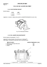
Page 197: ...oom with mounting pins The quickcoupling cylinders are controlled from the operator s compartment refer to QUICKCOUPLING Section 4 20 Before operating any mounted equipment make sure it has been fastened securely and that the locking pins have slid into the matching holes Fig 6 11 Quickcoupling 1 Tool Carrier 2 Hydraulic Cylinder 3 Locking Pin 6 9 2 BUCKETS FOR QUICKCOUPLING The following are the ...

Page 198: ...ing of a welded frame with a quickcoupling mounting hook and tine support The tines are forged in high quality steel The forklift can be applied for lifting transporting and loading materials stored in containers or on pallets as well as rocks of regular contour Specifications Lifting capacity 25300 N Tine length 1220 mm Tine spacing 840 1710 mm Weight 700 kG Fig 6 13 Forklift for Quickcoupling ...

Page 199: ...QUES Section 4 18 Fig 6 14 Multi purpose Bucket 6 9 5 515C LOADER HIGH DUMP BUCKET Bucket capacity with spillboard 1 77 m3 Application loading materials of the density up to 1300 kg m3 Performance increased in comparison with the standard bucket SPECIFICATION VALUE OF INCREASE in mm 1 Bucket pin axis height under load 610 2 Dump height 950 3 Reach 250 Fig 6 15 High dump Bucket 1 Bucket Frame 2 Buc...

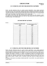
Page 200: ...ETRIC FASTENERS Chart 1 Nominal Thread Diameter mm Standard Torque 10 Nm 6 10 7 16 8 23 10 46 12 80 14 125 16 200 18 275 20 385 22 530 24 670 27 980 30 1330 33 1790 36 2325 6 11 TORQUE VALUES FOR STANDARD ENGLISH FASTENERS Chart 2 provides tightening torque for general purpose applications using original equipment standard hardware as listed in the Parts Catalog for the machine involved DO NOT SUB...

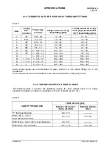
Page 201: ...e following chart 3 provides the tightening torques for split flange connections used in hydraulic systems Split flanges and fitting shoulders should fit squarely Install all bolts finger tighten and then torque evenly Overtorquing bolts will damage the flanges and or bolts which may cause leakage Chart 3 Bolt size in inches Flange size in inches Torque Value Nm 1 2 5 16 20 24 3 4 3 8 30 37 1 3 8 ...

Page 202: ...9 156 24 1 1 2 2 7 8 12 217 237 163 190 32 2 2 1 2 12 305 325 339 407 Above torque figures are recommended for plain cadmium or zinc plated fittings dry or wet installations These torques are not recommended for tube with wall thickness of 0 89 mm or less 6 14 TORQUE VALUES FOR HOSE CLAMPS The following chart 5 provides the tightening torques for hose clamps used in all rubber applications radiato...

Page 203: ...eel 1 4 7 16 20 16 23 15 20 15 20 12 18 3 8 5 8 18 27 33 23 38 23 38 20 25 1 2 3 4 16 47 54 38 46 38 46 28 36 5 8 7 8 14 61 68 45 53 45 53 34 32 3 4 1 1 6 12 72 80 49 57 49 57 45 53 1 1 6 14 72 80 49 57 49 57 45 53 6 16 TORQUE VALUES FOR AIR CONDITIONING O RING CONNECTIONS Chart 7 Thread Torque values for materials Nm Size size in inches Steel steel 1 4 7 16 20 15 25 3 8 5 8 18 27 33 1 2 3 4 16 40...

Page 204: ...g Bolts 3 4 380 Wheel lug nuts 1 M24x3 920 870 Counterweight fastening bolts 3 4 380 ROPS Cab to Frame Mounting Bolts 3 4 320 Ladder and Platform Fastening Bolts 1 2 108 Transmission Support to Frame Fastening Bolts 3 4 270 Transmission Support to Transmission Fastening Bolts 5 8 156 Engine mounting bolts 5 8 156 Steering wheel nut 1 2 48 Radiator Grill Fastening Bolts 1 2 108 Tightening torque to...

Page 205: ...ion System Pressure Filter 6 7 8 Engine Oil Drain Plug 7 1 1 8 ROPS Cab and ROPS Canopy Mounting Bolts 8 1 1 4 Axle Filler and Check Plug Axle Drain Plug Transmission Drain Plug 9 1 Wheel to Axle Fastening Bolts 10 12 Axle Breathers Brake Lines 11 13 Low Pressure Fuel Line Vent Screw on engine 12 14 Engine Valve Cover 13 15 Engine Valve Adjustment 14 19 18 Socket Wrench High Pressure Fuel Line Nut...

Reviews:

Related manuals for 515C