


MAINTENANCE
SECTION 5
Page 45
DRESSTA
OM515C520C99/1E
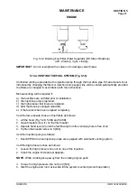
HYDRAULIC SYSTEM
IMPORTANT:
The reservoir must be refilled in this manner until the proper level is maintained after
the hydraulic system is operated at least five complete cycles (boom raise and lower plus bucket
close and dump operations).
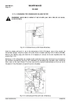
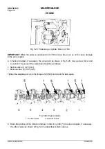
5.14.3. CHANGING THE HYDRAULIC OIL RETURN FILTER (Fig. 5.37)
Replace the oil filter according to the Maintenance Schedule or when the filter warning light comes
on (if equipped).
1. Drain the reservoir as described in section 5.14.2.
2. Remove filter element (1) from header (4) by turning the element counterclockwise (the filter is
located at the back of the reservoir).
3. Remove indicator assembly (2) from the element. Inspect and, if necessary, replace O-ring (5).
4. Remove and inspect O-ring (3); if worn or deteriorated, replace.
5. Install O-ring (3).
6. Place indicator assembly (2) in new filter element (1).
7. Apply a light coating of clean engine oil or chassis grease to the seal surface on new filter (1).
8. Install the new filter, turning it until the O-ring just contacts filter header (4).
9. Make aligning marks on the filter and the filter header; give the filter an additional ¼ to ½ turn.
IMPORTANT:
Do not overtighten the filter or use any tools for installation because this can
damage the O-ring or filter.
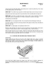
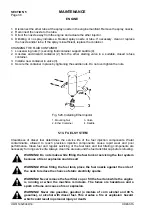
In CE version it is not necessary to drain the reservoir to replace the return filter. The oil level is
below the filter header and so the oil will not flow out of the reservoir while the element is being
removed. The element should be replaced when the filter warning light comes on.
To replace the filter element carry out as follow:
1. Remove cover (3) from filter header (2, Fig. 5.37A).
2. Remove old element (1) and replace it with a new one.
3. Clean the dismantled parts and install cover (3).
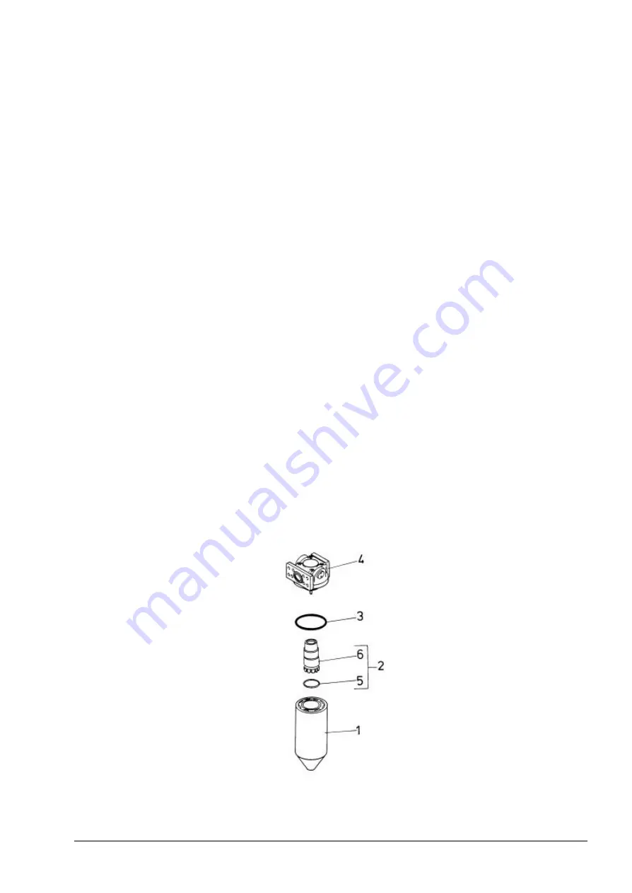
Fig. 5.37. Hydraulic Reservoir Return Filter
1. Filter Element
2. Indicator Assembly
3. O-Ring
4. Filter Header
5. O-Ring
6. Indicator
Summary of Contents for 515C
Page 3: ...OM515C520C99 1E DRESSTA ...
Page 5: ......
Page 7: ......
Page 10: ...SECTION 1 INTRODUCTION ...
Page 12: ......
Page 17: ...SECTION 2 SAFETY PRECAUTIONS ...
Page 19: ......
Page 37: ...SECTION 3 MACHINE TRANSPORT AND STORAGE ...
Page 39: ......
Page 49: ...SECTION 4 OPERATING ...
Page 51: ......
Page 107: ...SECTION 5 MAINTENANCE ...
Page 165: ...SECTION 6 SPECIFICATIONS ...
Page 167: ......
Page 181: ...SECTION 6 SPECIFICATIONS Page 16 OM515C520C99 1E DRESSTA WIRING DIAGRAMS ...
Page 182: ...SPECIFICATIONS SECTION 6 Page 17 DRESSTA OM515C520C99 1E WIRING DIAGRAMS ...
Page 187: ...SECTION 6 SPECIFICATIONS Page 22 OM515C520C99 1E DRESSTA WIRING DIAGRAMS ...