36
Dragon
Wave Inc.
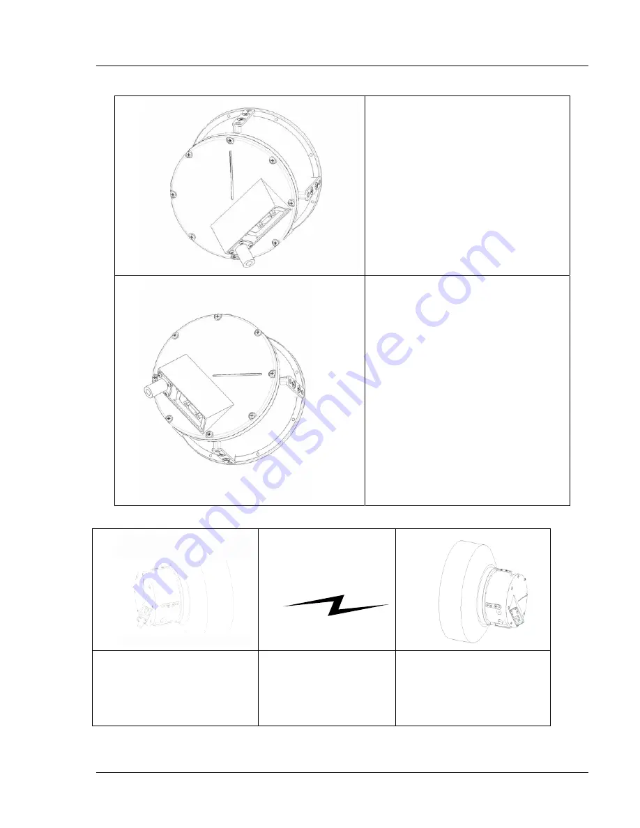
Perform this procedure to mount the 12
″
, 24”, 36
″
antennas and radios.
Vertical Polarization:
Groove on back plate is in vertical
orientation.
Cables point down and to the
right.
Horizontal Polarization:
Groove on back plate is in
horizontal orientation.
Cables point down and to the left.
One end MUST be
Vertical
Polarization
(backplate groove is
vertical)
The other end MUST be
Horizontal
Polarization
(backplate groove is
horizontal)
AirPair 100 UL 24 GHz Product Manual
Summary of Contents for AirPair 100-UL
Page 6: ...vi DragonWave Inc This page is intentionally blank AirPair 100UL 24GHz Product Manual ...
Page 8: ...viii DragonWave Inc This page is intentionally left blank AirPair 100UL 24GHz Product Manual ...
Page 12: ...4 DragonWave Inc This page is intentionally left blank AirPair 100 UL 24 GHz Product Manual ...
Page 16: ...8 DragonWave Inc This page is intentionally left blank AirPair 100 UL 24 GHz Product Manual ...
Page 42: ...34 DragonWave Inc This page is intentionally left blank AirPair 100 UL 24 GHz Product Manual ...
Page 47: ...Installation of Radio and Modem 39 Figure 5 Modem Version 2 0 ...
Page 49: ...Installation of Radio and Modem 41 Figure 8 24 GHz system with 24 antenna mounted Version 2 0 ...
Page 66: ...58 DragonWave Inc This page is intentionally left blank AirPair 100 UL 24 GHz Product Manual ...
Page 68: ...60 DragonWave Inc This page is intentionally left blank AirPair 100 UL 24 GHz Product Manual ...
Page 72: ...64 DragonWave Inc This page is intentionally left blank AirPair 100 UL 24 GHz Product Manual ...
Page 129: ...121 Appendix C Command Line Interface CLI This page is intentionally left blank Version 2 0 ...


