background image


IMS.OM.002949.DRM      

              Page 115 of 310 


                 Version 1.4 


   Doremi Labs 

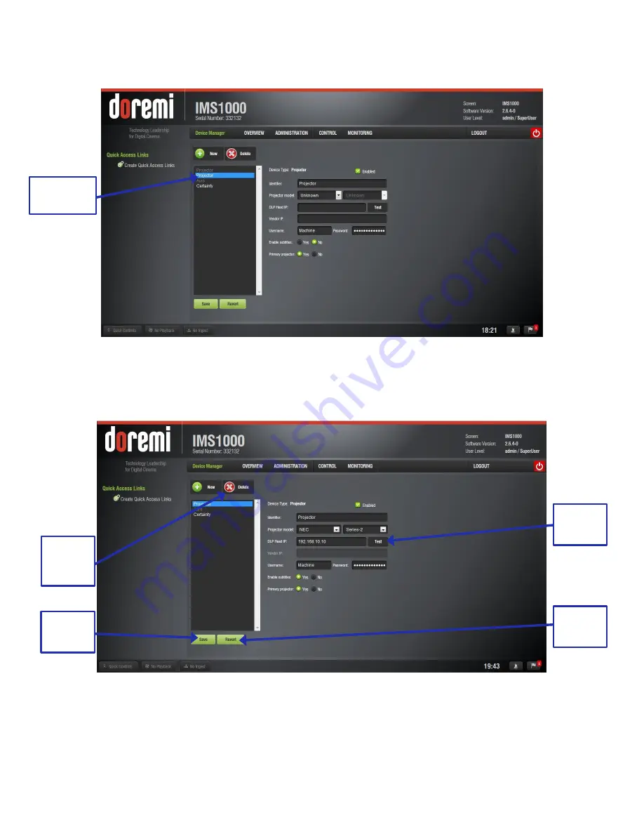
●  Select Projector. The following window will appear (Figure 125): 


Figure 125: Device Selection Window 

– Projector Item Selected 

The main configuration window will be updated to reflect the addition of the Projector device. 
The user will be able to enter the projector parameters (Figure 126): 


Figure 126: Device Manager GUI 

– Projector Fields Configuration 

To perform the projector configuration, follow the steps below: 

Delete 

Device 

Button 

Save 

Button 

Projector 

Selected 

Test 

Button 

Revert 
Button 

Summary of Contents for IMS1000

Page 1: ...of 310 Version 1 4 Doremi Labs IMS1000 Installation and User Manual Version 1 4 The English version of this document is the only legally binding version Translated versions are not legally binding and...

Page 2: ...I DCP playback 27 3 1 2 MPEG2 H264 VC1 MXF Interop 28 3 1 3 Video processing features 28 3 1 4 Security 28 3 1 5 Audio 28 3 1 6 Alternative Content 28 3 1 7 Pre Loaded Test Content 28 3 2 Input Output...

Page 3: ...stallation and Marriage with a Barco Series 2 Projector 53 5 1 Preparation 53 5 2 HDDs 55 5 3 Audio Cables Installation 57 5 4 GPI GPO Cables Installation 58 5 4 1 GPI GPO Pin Out Information 58 5 5 E...

Page 4: ...rs 84 9 Network Configuration 86 9 1 Default Network Configuration 86 9 2 Changing the IP Address 86 9 3 Network Reset 88 10 Time Zone Configuration 89 10 1 Checking the Time Zone 89 10 2 Changing the...

Page 5: ...4 Eight Channels 106 12 2 2 5 Nine Channels 107 12 2 2 6 ISDCF 108 12 2 2 7 Passthrough Configuration 109 12 2 2 8 Custom Mapping Configuration 109 12 2 3 SMPTE Packages 111 12 2 4 Audio Delay Configu...

Page 6: ...tor 123 12 4 1 Automation Cues 123 12 5 Macro Automation Cues 123 12 5 1 Macro Creation Using Macro Editor 123 12 5 2 Editing a Macro Automation Cue 124 12 5 3 Inserting Actions into Macro Cues 125 12...

Page 7: ...o a General Purpose Input Event 133 12 6 4 Connection to a Signal Event 134 12 6 5 Editing and Deleting the Event 135 12 6 6 Trigger Cue Saving 135 12 6 7 Pre Defined Macro Usage 136 12 6 8 Default Cu...

Page 8: ...cheduled Tasks Tab 149 12 12 Account Manager GUI 150 12 12 1 Add a New User Account 150 12 12 2 Edit an Existing User Account 152 12 12 3 Delete An Existing User Account 152 12 13 Theater Properties 1...

Page 9: ...Manual Back Up to RAID 168 12 17 4 2 Manual Back Up to External Drive 169 12 17 5 Deleting Backup File s 170 12 17 6 Restoring Backup File s 171 12 17 6 1 Restoring from RAID 171 12 17 6 2 Restoring...

Page 10: ...tton 191 13 4 Accessing a Show Playlist 192 13 4 1 Editing an Existing Show Playlist 192 13 4 2 Deleting a Show Playlist 193 13 4 3 Element Properties 194 13 4 4 Unencrypted CPLs 195 13 4 5 Encrypted...

Page 11: ...ent 215 13 7 5 Playback Lock Mode 215 13 7 6 Playback Alert Messages 216 13 8 CineLister Schedule Tab 218 13 8 1 How to Schedule Playback 218 13 8 2 Schedule Conflict 219 13 8 3 Scheduled Show Did Not...

Page 12: ...28 13 10 2 2 Information 229 13 10 2 2 1 Properties Tab 229 13 10 2 2 2 Assets Tab 230 13 10 2 2 3 SPL s Tab 230 13 10 2 2 4 KDM s Tab 232 13 10 2 2 5 Audio Mapping Tab 234 13 10 2 2 6 Settings Tab 23...

Page 13: ...red Tab 244 13 11 2 1 General Tab 244 13 11 2 2 System Tab 245 13 11 2 3 Colors Tab 246 13 11 2 3 1 HDMI Color Space Settings 247 13 11 2 3 2 HDSDI Color Space Settings 247 13 11 2 4 Info Tab 248 13 1...

Page 14: ...ive 267 15 3 Rebuilding a RAID 267 16 Troubleshooting 270 16 1 RAID Not Detected 270 16 2 Pre Loaded Test Content 270 16 3 Temporarily Setting the Network Configuration via USB 271 16 3 1 Permanently...

Page 15: ...cation 276 17 3 3 Solution 277 17 4 Audio Delay Issue 277 17 4 1 Description 277 17 4 2 Identification 277 17 4 3 Solution 277 17 5 Communication Issue with Dolby CP650 277 17 5 1 Description 277 17 5...

Page 16: ...ion Mid Playback 281 17 8 2 1 Description 281 17 8 2 2 Identification 281 17 8 2 3 Solution 283 17 8 3 Playback Stops In Between Clips 283 17 8 3 1 Description 283 17 8 3 2 Identification 283 17 8 3 3...

Page 17: ...1 3 Solution 287 17 12 Unit Not Booting When Drives Are Installed 287 17 12 1 Description 287 17 12 2 Identification 287 17 12 3 Solution 287 17 13 Green Screen Image 288 17 13 1 Description 288 17 13...

Page 18: ...ted Formats 297 22 Appendix E SDI Supported Formats 299 22 1 Video 299 22 2 Audio 299 23 Appendix F Connection Diagram 301 24 Appendix G Updating Web Based User Interface Version 303 25 Appendix H Ins...

Page 19: ...om support cinema support cinema warranties Hardware Warranty The hardware warranty can be found at the following location http www doremilabs com support cinema support cinema warranties HDMI The ter...

Page 20: ...art from voiding the warranty unauthorized engineers may touch live internal parts and receive a serious electric shock Do not put or allow anyone to put any object especially metal objects into the I...

Page 21: ...hard drives allows access to pins and traces supplying power to the hard drive backplane This is considered an energy hazard Removal of the hard drives must be performed by a trained service specialis...

Page 22: ...RSONNEL The lightning flash with the arrowhead symbol superimposed across a graphical representation of a person within an equilateral triangle is intended to alert the user to the presence of uninsul...

Page 23: ...higher for Series 2 Projectors 1 3 Contact Technical Support If in need of help or assistance please contact Doremi Labs Technical Services USA 24 7 Technical Services line 1 866 484 4004 Technical Se...

Page 24: ...IMS OM 002949 DRM Page 24 of 310 Version 1 4 Doremi Labs This page has been intentionally left blank...

Page 25: ...he work on static safe work surfaces work stations desks Make sure your desk and wrist strap ground outlets are connected to the building ground Be aware of the static generating materials that you wo...

Page 26: ...IMS OM 002949 DRM Page 26 of 310 Version 1 4 Doremi Labs This page has been intentionally left blank...

Page 27: ...ty theater management system supporting Doremi servers Ingest is done via USB eSATA or Ethernet 3 1 IMS1000 Key Features and Functions Doremi designed and manufactured Single board solution SMS and IM...

Page 28: ...up to 96KHz 3 1 6 Alternative Content HDMI input See Annex D for the list of supported formats HDSDI 1 5 Gbit Support Dual 3GSDI support is forthcoming Q3 2014 Live content network input Alternative...

Page 29: ...5 providing 2TB of media storage Raid 5 storage is hardware based The IMS1000 supports up to 4K 60fps and 2K HFR up to 120 fps The IMS1000 supports 500 Mbits s playback Battery IMS1000 battery is a P...

Page 30: ...identified as ETH0 eSATA Used for ingesting content at four times the maximum transfer rate of USB 2 0 USB There are three USB 2 0 ports on the front panel that can accommodate an external USB device...

Page 31: ...nal 1 GPI 0 2 GPI 0 3 GPI 1 4 GPI 2 5 GPI 2 6 GPI 1 7 GPI 3 8 GPI 3 GPO General Purpose Output for Automation Interface RJ 45 Connector Pin Signal 1 GPO 0 2 GPO 1 3 GPO 2 4 GPO 4 5 GPO 5 6 GPO 3 7 5 V...

Page 32: ...45 Connector Channels 1 8 Signal 1 Channel 9 10 plus 2 Channel 9 10 minus 3 Channel 11 12 plus 4 Channel 13 14 plus 5 Channel 13 14 minus 6 Channel 11 12 minus 7 Channel 15 16 plus 8 Channel 15 16 min...

Page 33: ...IMS OM 002949 DRM Page 33 of 310 Version 1 4 Doremi Labs This page has been intentionally left blank...

Page 34: ...o install the IMS1000 into your projector be sure that o The projector is powered down and in the off position o Disconnect the AC power cord from the wall o Remember to always follow ESD procedures 4...

Page 35: ...rojector cover in place Figure 8 Figure 8 Screw Locations Using the key for the projector screen turn the key in the lock to the right so that it is unlocked Figure 9 Figure 9 Projector Unlock Gently...

Page 36: ...i Labs Figure 10 Projector Cover Removed Remove the blank cover of the media block slot by unscrewing the two handles at the side Figure 11 Figure 11 Unscrewing the Slot Cover The media block slot sho...

Page 37: ...S1000 from its carton and antistatic bag Gently place the IMS1000 board into the projectors media block slot guiderails on the inside of the slot Figure 12 and Figure 13 Figure 13 Missing HDDs Screw i...

Page 38: ...g SATA I drives with SATA II drives within the same RAID Each one of the three HDDs that come with the IMS1000 will be labeled with a 1 2 or 3 The HDD labeled 1 is to be inserted into the left hand HD...

Page 39: ...the carrier handle open insert the drive all the way into the chassis cage Figure 16 Figure 16 HDD Insertion Close the silver HDD carrier handle until you hear an audible click and the release tab ha...

Page 40: ...Covers Reattach the projector cover and screw in the four screws holding it in place Figure 18 Figure 18 Reattaching the Projector Cover Turn the key to lock the projector in place Figure 19 Figure 1...

Page 41: ...other end of the shielded CAT5 or CAT6 cable into the audio processor Take another shielded CAT5 or CAT6 cable and plug the end into the connector labeled AES OUT 9 16 Figure 21 Plug the other end of...

Page 42: ...r more information on ferrite core clamp installation Plug the other end of the shielded CAT5 or CAT6 cable into whichever automation controller is available or required Take another shielded CAT5 or...

Page 43: ...network switch Figure 25 Install a ferrite core clamp near the connector closest to the IMS1000 Refer to Section 25 for more information on ferrite core clamp installation Figure 25 Ethernet Connecto...

Page 44: ...igure 27 Please refer to the projector manufacturer manual for proper power up sequence Figure 27 Power Switch 4 8 Accessing the GUI To access the IMS1000 GUI Graphical User Interface launch your brow...

Page 45: ...ith the IMS1000 the projector must be configured in the Device Manager While the projector is booting up configure the device in the Device Manager To access the Device Manager go to Administration De...

Page 46: ...Page 46 of 310 Version 1 4 Doremi Labs Figure 29 Add Projector Drop Down Populate the projector parameters that appear Figure 30 Figure 30 Projector Added Click the Save button Figure 30 Projector Sel...

Page 47: ...ema Communicator for S2 DCC If you do not have the latest version installed contact your administrator When first opened the Communication Settings window will appear Input the IP address of the proje...

Page 48: ...o obtain the password contact your administrator Figure 33 Figure 33 Control Mode Window Using the Arrow button in the window that appears scroll until the Setup button is available Click on the Setup...

Page 49: ...i Labs Figure 35 Setup Window In the Option Slot window select IMB from the drop down and click Apply Figure 36 Figure 36 Option Slot Window Click the Installation button and then click the Re Marriag...

Page 50: ...d login Contact your administrator for the necessary information Click the Re Marriage button Figure 38 Figure 38 Re Marriage Login A window will appear stating that the operation was successful Click...

Page 51: ...e projector Contact your administrator for the password Figure 40 Figure 40 Projector Menu To ensure that the marriage was completed correctly on the IMS1000 GUI go to Monitoring Diagnostics Media Blo...

Page 52: ...IMS OM 002949 DRM Page 52 of 310 Version 1 4 Doremi Labs This page has been intentionally left blank...

Page 53: ...install the IMS1000 into your projector be sure that o The projector is powered down and in the off position o Disconnect the AC power cord from the wall o Remember to always follow ESD procedures 5 1...

Page 54: ...hould now be empty Figure 44 Figure 44 Empty Media Block Slot Carefully remove the IMS1000 from its carton and antistatic bag Gently place the IMS1000 board into the projectors media block slot guider...

Page 55: ...ing SATA I drives with SATA II drives within the same RAID Each one of the three HDDs that come with the IMS1000 will be labeled with a 1 2 or 3 The HDD labeled 1 is to be inserted into the left hand...

Page 56: ...the carrier handle open insert the drive all the way into the chassis cage Figure 47 Figure 47 HDD Insertion Close the silver HDD carrier handle until you hear an audible click and the release tab ha...

Page 57: ...AT6 cable into the audio processor Take another shielded CAT5 or CAT6 cable and plug the end into the connector labeled AES OUT 9 16 Figure 49 Plug the other end of the shielded CAT5 or CAT6 cable int...

Page 58: ...ation Plug the other end of the shielded CAT5 or CAT6 cable into whichever automation controller is available or required Take another shielded CAT5 or CAT6 cable and plug the end into the IMS1000 con...

Page 59: ...formation on ferrite core clamp installation Figure 53 Ethernet Connections Note Ethernet port Eth0 is set to DHCP by default All IMS1000 boards are shipped from the factory with the following default...

Page 60: ...about a 2 30 minutes Figure 56 Please refer to the projector manufacturer manual for proper power up sequence Figure 56 Power Switch 5 7 Accessing the GUI To access the IMS1000 GUI Graphical User Inte...

Page 61: ...icating that the board and the projector are not married If there is a touch screen attached to the projector two tamper errors will appear indicating that the marriage has not occurred Figure 57 Figu...

Page 62: ...ge has been completed the Key button will turn green Figure 59 and the taillight will also turn green Figure 59 Green Key Button To ensure that the marriage was completed correctly on the IMS1000 GUI...

Page 63: ...IMS OM 002949 DRM Page 63 of 310 Version 1 4 Doremi Labs This page has been intentionally left blank...

Page 64: ...The projector is powered down and in the off position o Disconnect the AC power cord from the wall o Remember to always follow ESD procedures 6 1 Preparation Figure 61 Christie Projector Remove the bl...

Page 65: ...tic bag Gently place the IMS1000 board into the projectors media block slot guiderails on the inside of the slot Figure 63 The latches must be out and open for the IMS1000 to fit properly To open the...

Page 66: ...ity Doremi prohibits mixing SATA I drives with SATA II drives within the same RAID Each one of the three HDDs that come with the IMS1000 will be labeled with a 1 2 or 3 The HDD labeled 1 is to be inse...

Page 67: ...e Figure 66 With the carrier handle open insert the drive all the way into the chassis cage Figure 67 Figure 67 HDD Insertion Close the silver HDD carrier handle until you hear an audible click and th...

Page 68: ...rted 6 3 Audio Cables Installation Figure 69 Audio Connectors Plug one shielded CAT5 or CAT6 cable end into the connector labeled AES OUT 1 8 on the IMS1000 board Figure 69 Plug the other end of the s...

Page 69: ...ed to use the RJ 45 to DB25 converter that is provided with the IMS1000 Figure 70 Figure 70 RJ 45 to DB25 Converter 6 4 GPI GPO Cables Installation Figure 71 GPI GPO Connectors Plug one shielded CAT5...

Page 70: ...end of the shielded CAT5 or CAT6 cable into whichever automation controller is available or required 6 4 1 GPI GPO Pin Out Information Figure 72 RJ45 Socket Pin Out 6 5 Ethernet Cables Connect an Ethe...

Page 71: ...Eth1 o IP 192 168 100 50 o SM 255 255 255 0 o GW 192 168 100 1 For more information refer to Section 23 6 6 Power on Projector Connect AC power to the projector Figure 74 Figure 74 AC Power After abo...

Page 72: ...own menu make sure that Doremi is selected Figure 77 Figure 76 Content Devices Configuration Figure 77 Drop Down Menu Turn the projector on by pressing the green Power button on the touch panel contro...

Page 73: ...Figure 79 Error Message 6 7 Accessing the GUI After about forty more seconds the board will be fully powered on and the user will be able to access the web GUI To access the IMS1000 GUI Graphical Use...

Page 74: ...he Device In order for the projector to communicate with the IMS1000 the projector must be configured in the Device Manager When the projector and board have finished booting up configure the device i...

Page 75: ...Page 75 of 310 Version 1 4 Doremi Labs Figure 81 Add Projector Drop Down Populate the projector parameters that appear Figure 82 Figure 82 Projector Added Click the Save button Figure 82 Projector Sel...

Page 76: ...ch panel controller attached to the projector will show a second error window indicating that the marriage has not occurred Figure 83 Press the Acknowledge button Figure 83 Error Window Go to Menu Ser...

Page 77: ...IMS OM 002949 DRM Page 77 of 310 Version 1 4 Doremi Labs Figure 85 Marriage Wizard When the Marriage Checklist window appears click Next Figure 86 Figure 86 Marriage Checklist Next Button Next Button...

Page 78: ...n is pressed the user has 30 seconds to press the Marriage button on the projector which should now be green Figure 87 and Figure 88 Figure 87 Arm Marriage Window Figure 88 Marriage Button on Projecto...

Page 79: ...ctor Light To ensure that the marriage was completed correctly on the IMS1000 GUI go to Monitoring Diagnostics Media Block The Security Manager section should appear as it does below Figure 90 Figure...

Page 80: ...IMS OM 002949 DRM Page 80 of 310 Version 1 4 Doremi Labs This page has been intentionally left blank...

Page 81: ...wait two minutes The LED lights on the IMS1000 will stop flashing and the HDD lights will have a steady light once it has finished shutting down After two minutes refer to the projector manufacturer m...

Page 82: ...IMS OM 002949 DRM Page 82 of 310 Version 1 4 Doremi Labs This page has been intentionally left blank...

Page 83: ...and the password is doremi However the administrator may have changed and or added other login usernames and passwords Please contact your administrator for the appropriate information Figure 92 Login...

Page 84: ...rator Super User Manager ShowManager Root Administrator Ingest Projection Doremi Projection Figure 94 Password Confirmation Window In Figure 94 the user is asked to select the username and password No...

Page 85: ...IMS OM 002949 DRM Page 85 of 310 Version 1 4 Doremi Labs This page has been intentionally left blank...

Page 86: ...o the Administration Tab Control Panel Networking Configuration and then follow the steps below Figure 95 Figure 95 Networking Configuration Window The Networking Configuration window will appear You...

Page 87: ...ep these settings See your system administrator for this password SuperUser privileges are necessary to be able to confirm the changes If the user is already logged in with SuperUser privileges a pass...

Page 88: ...eset If for any reason the network settings need to be reset go to Administration Control Panel Networking Configuration and click the Revert button located on the bottom of the screen Figure 97 Figur...

Page 89: ...t to Pacific Time Zone PST or PDT This section provides information on how to check and or change the time zone 10 1 Checking the Time Zone To check the time and time zone go to Administration Control...

Page 90: ...is installed Once the appropriate timezone has been selected and appears within the box labeled Timezone click the Update button to save this setting Figure 99 SuperUser privileges are necessary to sa...

Page 91: ...op Down Window Once the appropriate time change has been selected and appears within the box labeled Change Time click the Update button to save this setting Figure 100 SuperUser privileges are necess...

Page 92: ...rs that sync the time and date on your unit to the UTC time To access the NTP Servers tab click on the green arrow button on the right side of the Date and Time tab found by going to Administration Co...

Page 93: ...IMS OM 002949 DRM Page 93 of 310 Version 1 4 Doremi Labs This page has been intentionally left blank...

Page 94: ...quick access to the user for its respective function From the top Tabs Bar the user can navigate to the Administration Tab Control Tab or the Monitoring Tab Figure 102 Overview Tab 11 1 Notification B...

Page 95: ...Quick Controls button again will cause the window to close 11 1 2 Playback The Playback button will alert the user to any playback that is in progress Figure 104 If playback is in progress clicking o...

Page 96: ...The Ingest button will alert the user to any ingest that is in progress Clicking on the button will open the Ingest Monitor tab that displays the ingest progress Figure 105 For more information on in...

Page 97: ...he Session Viewer window Clicking on the button again will cause the window to close Figure 106 Figure 106 Session Viewer Window 11 1 5 Notifications The Notifications button provides the user with no...

Page 98: ...ton again will cause the window to close Hovering over the More Details button provides more details about the notification Figure 107 To delete a notification highlight it and click on the X that app...

Page 99: ...IMS OM 002949 DRM Page 99 of 310 Version 1 4 Doremi Labs This page has been intentionally left blank...

Page 100: ...nnect to other servers Once connected the specified servers will show in the Ingest Manager and there they will be able to pull ShowPlaylists CPLs KDMs and Doremi Licenses Macro Editor Allows the user...

Page 101: ...ill be sent to o Log Operator Maintenance Allows the user to log important information e g hard disk replacement projector lamp replacement etc This application helps the system administrator keep tra...

Page 102: ...This is a pre set configuration 8 channels This is a pre set configuration 9 channels This is a pre set configuration ISDCF This is a pre set configuration Passthrough This is a pre set configuration...

Page 103: ...CPL s Center C audio channel Ch 04 is Input Ch 04 is pass through meaning the output channel X will be playing the CPL s audio channel X Ch 05 is Surround S Output ch 05 will be playing the CPL s Surr...

Page 104: ...ll be playing the CPL s LFE Screen Sub Woofer audio channel Ch 05 is Left Surround Ls Output ch 05 will be playing the CPL s Left Surround Ls audio channel Ch 06 is Right Surround Rs Output ch 06 will...

Page 105: ...06 is Right Surround Rs Output ch 06 will be playing the CPL s Right Surround Rs audio channel Ch 07 is Input Ch 07 is pass through meaning the output channel X will be playing the CPL s audio channe...

Page 106: ...ch 05 will be playing the CPL s Left Surround Ls audio channel Ch 06 is Right Surround Rs Output ch 06 will be playing the CPL s Right Surround Rs audio channel Ch 07 is Left Center Lc Output ch 07 wi...

Page 107: ...udio channel Ch 06 is Right Surround Rs Output ch 06 will be playing the CPL s Right Surround Rs audio channel Ch 07 is Left Center Lc Output ch 07 will be playing the CPL s Left Center Lc audio chann...

Page 108: ...dio channel Ch 07 is HI Output ch 07 will be playing the CPL s Hearing Impaired HI audio channel Ch 08 is VI Output ch 08 will be playing the CPL s Narration VI audio channel Ch 09 is Left Center Lc O...

Page 109: ...This configuration allows the CPL s audio channel to passthrough to the processor Figure 117 Figure 117 Audio Mapping Set to Passthrough 12 2 2 8 Custom Mapping Configuration Click on the drop down m...

Page 110: ...abs Click on the drop down arrow to view the available mapping parameter selection for each output channel ch 01 ch 16 to select the CPL s audio channel using its label that is to be routed to the pro...

Page 111: ...g Drop Down Window Make sure to click the Save button to ensure the configuration is saved SuperUser privileges are necessary to save changes Figure 121 The list of possible labels that can be routed...

Page 112: ...arrow button the right side of the Channel Mapping tab Figure 120 All audio tracks will be modified for the same delay selected After the delay has been configured click on the green Save button to sa...

Page 113: ...MXF files do not contain any channel label information Therefore if a configuration is selected the routing will be executed as if the audio MXF file was created according to the ISDCF audio mapping...

Page 114: ...for the control of theater automation devices To run the Device Manager go to Administration Device Manager The following window will appear Figure 123 Figure 123 Device Manager 12 3 1 Adding a Projec...

Page 115: ...elected The main configuration window will be updated to reflect the addition of the Projector device The user will be able to enter the projector parameters Figure 126 Figure 126 Device Manager GUI P...

Page 116: ...pear Clicking the Revert button prior to saving will delete the unsaved information Figure 126 12 3 1 1 Removing a Device or Projector To remove a device or projector click on it in the left part of t...

Page 117: ...Nior The Device Manager GUI will be updated to reflect the addition of the JNior device Input the JNior Server IP address in the appropriate field Figure 128 The port number field will already contain...

Page 118: ...ing a Raw Device A Raw device allows for communication with an external device across an Ethernet connection using Raw data formatted as text or binary strings To add a Raw device click the New button...

Page 119: ...If the user is already logged in with SuperUser privileges the password confirmation window will not appear Clicking the Revert button prior to saving will delete the unsaved information Figure 126 12...

Page 120: ...Labs Technical Support Section 1 3 or visit http www doremilabs com support cinema support cinema manuals captiview manuals 12 3 8Subtitle Engine Configuration This section provides instructions on h...

Page 121: ...126 The user will be asked for a password Enter the appropriate password and press Ok Clicking the Revert button prior to saving will delete the unsaved information Figure 126 12 3 9 Missing License...

Page 122: ...age 122 of 310 Version 1 4 Doremi Labs If the user tries to add the device with the missing license a message will alert them to the missing license Figure 132 Figure 132 Missing License Message Missi...

Page 123: ...n Cues A Macro Automation Cue consists of two parts an Automation Cue and a Trigger Cue Trigger Cues are explained fully in the Section 12 6 Trigger Cues A Trigger Cue is an action that is sent to the...

Page 124: ...already logged in as a SuperUser the confirmation window will not appear 12 5 2 Editing a Macro Automation Cue To remove delete a Macro Automation Cue select it in the Macro Editor window and click th...

Page 125: ...sponding action and click the Insert button Figure 136 The actions available include the following Projector Dowser open or close the selected projector dowser Lamp power on or off the selected projec...

Page 126: ...e To add a GPO action highlight the desired Macro Cue Select the General Purpose Output option which is located in the Input Output section in the Select an Action to Insert drop down menu Figure 136...

Page 127: ...Output Actions option which is located in the Playback section in the Select an Action to Insert drop down menu Figure 136 Click the Insert button The following window will appear Figure 139 Figure 1...

Page 128: ...e name of the projector from the drop down menu window that appears Figure 141 Use the plus minus buttons to select the channel to send the command to Click the Ok button 12 5 9 Automation Library Usa...

Page 129: ...n Click the Ok button or Cancel to cancel this command 12 5 9 2 Resulting Macro Setting The right part of the Automation Cue tab will display the added actions as illustrated below Figure 143 Figure 1...

Page 130: ...o the Macro Automation Cue 12 5 10 3 Action and Macro Removal To remove an action from the list of actions associated with a Macro Automation Cue select the action in the Macro Actions window and clic...

Page 131: ...Editor or by clicking on the Trigger Cue arrow in the Macro Automation tab and Quick Controls tab Figure 143 Note The Signal comes from an external device connected over the Ethernet The external dev...

Page 132: ...he Trigger Cue in a Show Playlist The newly created Trigger Cue will appear in the Trigger window and it will be ready to connect to an event Figure 146 Figure 146 Trigger Cue Defined To edit the name...

Page 133: ...re 147 Figure 147 Events Window To connect the selected Trigger Cue to a GPI event click the General Purpose Input option and click the Add button Figure 147 The following window will appear Figure 14...

Page 134: ...you want to assign the Signal event to Click the Connect to an Event button from Macro Editor s Trigger Cue tab The Connect to an Event drop down window will appear Figure 147 Click the Signal button...

Page 135: ...e the event Figure 151 12 6 6 Trigger Cue Saving Repeat the Trigger Cue creation operation for all Trigger Cues that are created and click the Save button Figure 151 Clicking the Revert button before...

Page 136: ...ded from the Macro Editor GUI 12 6 8 Default Cues The default_cues xml file can be used to load an automation and trigger cues playlist prior to any playback This is to avoid having to add a Fire Alar...

Page 137: ...ls arrow on the right side of the GUI Figure 151 12 7 1 Creating Macros To create macros refer to Section 12 5 12 7 2 Setting up Quick Controls All of the macros created in the Macro Automation tab wi...

Page 138: ...tion highlight it Several options will appear on the right Figure 154 o To delete the section entirely click on the X to the right of the section o To delete a macro within the section click on the X...

Page 139: ...trols button on the bottom left corner in the Notification Bar and the recently added macros will appear in the Quick Controls window Click on previously created macro to execute it from any tab on th...

Page 140: ...IMS OM 002949 DRM Page 140 of 310 Version 1 4 Doremi Labs Figure 155 Quick Controls Window Quick Controls Button Macros Available...

Page 141: ...Advanced Options Clicking the Advanced Options button will open a drop down menu where the user can configure the following file types to be used for ingesting Figure 156 Authorize play while ingest f...

Page 142: ...7 Add New Server Enter the Identifier name in the Identifier field It is recommended that a unique identifier be used e g screen 1 screen 2 etc The Ingest Protocol is set at FTP Enter the IP address f...

Page 143: ...y3D RealD 4K Enabled etc Show Playlist click this box to be able to export and then import a SPL from one server to another Click the Save button to save the configuration The server is now added to t...

Page 144: ...ersion 1 4 Doremi Labs Figure 158 Ingesting This will populate the Ingest Manager application scan tab window with all the content available for ingest from the selected source feed unit Select the de...

Page 145: ...mi Labs 12 9 Terminal To log into the Terminal tab Administration tab Terminal enter the admin user login name and password Figure 159 Figure 159 Terminal Login If possible all changes made to setting...

Page 146: ...ck on the Standby button Figure 160 The user will be asked to confirm the operation Figure 160 System GUI If content is currently being played a window will appear asking the user to confirm the resta...

Page 147: ...records created with the Log Operator Maintenance application are stored for one year The Log Operator Maintenance application is available in Administration Control Panel Log Operator Maintenance Th...

Page 148: ...e job performed as accurately as possible This will be used for future references about maintenance The log will be recorded based on the date and time when the log was entered into the Log Operator M...

Page 149: ...eration the last time the operation was performed and the next time the operation will have to be performed For the IMS1000 the only type of maintenance operation is annual maintenance activities The...

Page 150: ...ager The following window will appear Figure 166 Figure 166 Account Manager GUI The Account Manager GUI allows the user to edit add and delete user accounts 12 12 1 Add a New User Account To add a new...

Page 151: ...allowed to ingest and delete content and to save ShowPlaylists SuperUser In addition to Show Manager s right a SuperUser has the privileges to configure the unit and to create modify and delete user a...

Page 152: ...ername or the login type Figure 170 Figure 170 Account Manager GUI User Properties Editing Click the Save button when finished editing the settings Click the Close button when finished with the config...

Page 153: ...istration Control Panel Theater Properties This information is necessary as it contains information needed for the generation of the FLM file The information is used by studios in KDM management 12 13...

Page 154: ...for the facility Figure 173 Figure 173 Contacts Tab Click on the New button Figure 173 The Add Contact window will appear Figure 174 Fill out the appropriate information and click Save or Cancel to c...

Page 155: ...the arrow at the right side of the Theater Properties tab Figure 173 Here the user can input the facility s name and address Click the Save button to save the changes Clicking the Revert button withou...

Page 156: ...e GUI The links are available on every tab of the GUI To access the Quick Access Links application go to Administration Control Panel Quick Access Links or click on the Quick Access Links tab on the l...

Page 157: ...in the window Figure 178 Figure 178 Link Added To edit the link highlight the link Figure 179 To delete the link click the X To rename the link click the rectangle To revert to the default name click...

Page 158: ...ert button will delete all unsaved changes Figure 179 After saving and refreshing the newly added link will appear on the left hand side of the GUI in all tabs Figure 180 Clicking on the link will aut...

Page 159: ...ation go to Administration Control Panel Cinelister Configuration Figure 181 12 15 1 Editor Configuration Figure 181 Cinelister Configuration Editor To modify the amount of time that the fast forward...

Page 160: ...on To modify the first day of the week in the Cinelister Schedule tab select the day from the drop down menu Figure 182 Figure 182 Cinelister Configuration Schedule Click Save to save the changes and...

Page 161: ...can be added to Show Playlists in Cinelister To access the Live Manager GUI go to Administration Control Panel Live Manager Figure 183 Figure 183 Live Manager 12 16 1 Creating a Live Event To create a...

Page 162: ...Figure 185 Enter the IP address of the external Live Event in the Device IP field Figure 185 Figure 185 CPL Title and IP Click the Create button to complete the live CPL creation Figure 186 The Live...

Page 163: ...PL and click on the Properties button on the right hand side Figure 186 Figure 187 CPL Properties This information is the same information provided in the Content Manager Composition Playlist tab Figu...

Page 164: ...Playlist 12 16 3 Deleting a Live CPL To delete an existing live CPL select it in the Composition Playlist tab of the Content Manager application Click the Delete button Figure 189 Figure 189 Deleting...

Page 165: ...these files daily The most recent backup is restored The user can manually back up files to the local drive or external drive e g e SATA or USB or restore from an external drive at any time Note Supp...

Page 166: ...Figure 191 Yes The user can choose to restore now by clicking on Yes This will restore the configuration files on the RAID to the new SSD flash drive No The user can choose not to restore now by clic...

Page 167: ...o Note You may cancel at any time by clicking on the Cancel button Figure 192 Restore Process Window Click on the Close button to exit out of the Restore window To view the backup go to the Restore B...

Page 168: ...Figure 193 Backup The following window will appear Figure 194 Select the location where you want to save the backup file You can either save to local disk RAID or to an external drive Click on the Ok...

Page 169: ...to an external drive e g e SATA or USB follow the instructions in this section Insert an external storage device into the unit For this example a USB flash drive will be used Click on Generate Backup...

Page 170: ...98 Figure 198 USB Restore o Note The USB backup will only appear if the USB or external device is plugged in The manual backup process is now complete 12 17 5 Deleting Backup File s If you want to del...

Page 171: ...and click on the Restore button Figure 201 Figure 201 Restore Button A log in screen will appear Enter the appropriate password and click on OK The Restore Category Selection window will appear Figur...

Page 172: ...ight the item on the left and click on the Restore button The Processing window will appear Figure 203 You will be required to reboot the system to complete the restore process To reboot the system go...

Page 173: ...assword and click on OK The Restore Category Selection window will appear Figure 205 Here you will be able to choose which types of files to restore or you can select all files to restore o Doremi The...

Page 174: ...ssing window will appear Figure 206 Figure 206 Processing Window You will be required to reboot the system to complete the restore process To reboot the system go to the System tab Figure 206 If you d...

Page 175: ...er has not agreed to the terms and conditions yet a notification will appear at the top of the screen informing the user that he she will need to give their consent Figure 207 Figure 207 License Messa...

Page 176: ...IMS OM 002949 DRM Page 176 of 310 Version 1 4 Doremi Labs Figure 208 License Agreement Check Box...

Page 177: ...equency To access the Automatic Log Upload Manager go to Administration Control Panel Automatic Log Upload Manager Figure 209 Check the Active Log Uploading check box to ensure that the logs are being...

Page 178: ...nter a username and password Select SMPTE and or System logs Use the Test button to test the configuration if desired Figure 210 Click OK and the new configuration will appear in the main window Click...

Page 179: ...h tab lists the high and low threshold as well as the hysteresis value which is optional The default hysteresis value is 0 but this can be changed The hysteresis value is the plus or minus tolerance v...

Page 180: ...ures Tab 12 20 2 Voltages Tab The Voltages tab lists the high and low threshold values for different components of the server in millivolts Hovering over the component will give a brief explanation of...

Page 181: ...to save any changes and Revert to undo any unsaved changes Figure 215 Figure 215 Fans Tab 12 20 4 Counters Tab The Counters tab lists the high and low threshold values for different errors indicating...

Page 182: ...310 Version 1 4 Doremi Labs Figure 216 Counters Tab 12 20 5 Reset to Default Tab The Reset to Default tab allows the user to reset all values to the default values Figure 217 Figure 217 Reset Values...

Page 183: ...IMS OM 002949 DRM Page 183 of 310 Version 1 4 Doremi Labs This page has been intentionally left blank...

Page 184: ...CineLister GUI go to Control CineLister The user will be prompted to CineLister s Playback tab The Playback tab is the default tab that CineLister displays every time the application is opened Figure...

Page 185: ...that can be used when creating a SPL Audio visual content e g features test content trailers live etc Automation cues Macro automation events Trigger cues events upon which a Macro Automation Cue is...

Page 186: ...to Create a New Show Playlist Figure 220 Editor Tab Click on the New button from the CineLister Editor tab Figure 220 Click on the elements to add to the SPL from the left pane of the GUI Figure 220 T...

Page 187: ...ton Figure 221 The user will be prompted to a window asking them to input the correct password SuperUser privileges are necessary to confirm the changes If the user is already logged in with SuperUser...

Page 188: ...ht side of the application Select the macro on the left part of the GUI and click on it Figure 223 Figure 223 Macro Selected The Edit Time Code window will appear Figure 224 Figure 224 Edit Time Code...

Page 189: ...dded 13 3 1 2 Adding a Trigger Cue Select the element to attach the Trigger Cue to in the SPL on the right side of the application Select a Trigger Cue on the left part of the GUI and click on it Figu...

Page 190: ...the Automation Cue to associate to the Trigger by clicking on it in the Automation Cues window Select the scope of the trigger by checking if the trigger is available for all elements or just the sele...

Page 191: ...ated with an automation or trigger cue the cues will also be re ordered 13 3 2 1 Refresh Button Anytime new content and a package are ingested into the server the items will not be displayed automatic...

Page 192: ...he desired SPL Figure 230 Figure 230 Open SPL Select the desired SPL and click the Ok button The Show Playlist will be displayed on the right side of the GUI 13 4 1 Editing an Existing Show Playlist C...

Page 193: ...L highlight the CPL and click on the Properties icon that appears on the right Figure 231 13 4 2 Deleting a Show Playlist Open the desired SPL Once the SPL is opened delete it by clicking on the Delet...

Page 194: ...4 3 Element Properties To view the properties of any element in a Show Playlist select the element from the right side of the GUI Highlight the selected item and click on the Element Properties butto...

Page 195: ...ar Figure 234 Figure 234 Unencrypted CPL 13 4 5 Encrypted CPL with Valid KDM If the element selected is an encrypted CPL the following Properties window will appear with the KDM information The window...

Page 196: ...matically make the content 3D The content must be in 3D 48fps format to create a 3D SPL 13 5 2 How to Set the Show Playlist Mode to 3D Click the Show Playlist Properties button Figure 231 Select the 3...

Page 197: ...s mode the IMS1000 video output is in the YCxCz color space The projector itself needs to be properly configured to the YCxCz color space in 3D or 48fps mode for proper display Contact the projector v...

Page 198: ...238 Plus Button 13 6 1 Segment A segment allows the user to organize and arrange the visual presentation of a ShowPlaylist SPL into sections or segments Segments are only used as an aesthetic tool to...

Page 199: ...tton to save the name o Substitute any spaces with an underscore o Note Within the same SPL each segment must have a different name Figure 240 New Segment Naming Use the up and down arrows to rearrang...

Page 200: ...External Show Playlists The External Show Playlist allows the content of that SPL to be inserted into the current SPL CineLister now lists the available SPLs on the left area of the editor among the o...

Page 201: ...nges 13 6 1 2 Skip to ShowPlaylist Segment Macro The user can also create a macro that will cause playback to jump to a specific segment To create the macro go to Administration Macro Editor In the Ma...

Page 202: ...macro and click OK Figure 244 Figure 244 Macro Settings The macro will appear in the window Highlight the macro and click on Select an Action to Insert Figure 245 Figure 245 Macro Added In the window...

Page 203: ...the exact name of the segment in the field that appears and click OK Figure 247 Figure 247 Segment Named The newly added macro will appear in the Macro Editor Click the Save button to save the macro T...

Page 204: ...lly for user information purposes only The exception is the Exit_Intermission marker For information on how to use this marker go to Section 13 6 3 3 1 13 6 3 Intermission The Intermission feature off...

Page 205: ...add to the Main SPL Figure 249 shows an example of an Intermission SPL Figure 249 Intermission SPL Click the Save button and name the SPL Figure 249 13 6 3 2 Main SPL Create or open the Main SPL that...

Page 206: ...down that appears select Intermission Figure 251 Figure 251 Intermission Drop Down In the window that appears select the preferred offset position time code the Intermission Playlist from the drop do...

Page 207: ...Figure 253 Click the Save button and name the SPL if necessary Figure 253 Figure 253 Intermission SPL Added In the Cinelister Playback tab the Main SPL will appear as shown in Figure 254 The CPL that...

Page 208: ...n to the Main SPL or with a marker jump to a specific part of the Intermission SPL To create the macro go to the Macro Editor Administration Macro Editor In Macro Editor click on the New button Figure...

Page 209: ...Select Exit from Intermission from the drop down menu and click OK Figure 258 Figure 258 Exit from Intermission Click the Save button and enter the necessary password to save Figure 259 SuperUser priv...

Page 210: ...of part two of the Main SPL To cause playback to jump to a specific part of the Intermission SPL instead of returning to the Main SPL the user can create a marker that works with the macro To add a ma...

Page 211: ...Exit Intermission Marker The marker has now been added During intermission when the Exit from Intermission macro is triggered playback will jump to the time code indicated by the marker Figure 262 Fig...

Page 212: ...the right hand side of the GUI in the Editor and Schedule tabs Figure 237 13 7 1 Playback an Existing SPL Click on the Open button from the CineLister Editor tab Figure 237 The following window will a...

Page 213: ...Playlist is selected a message will appear stating The show playlist is empty Figure 265 Figure 265 Empty Playlist Note If a SPL contains an element with an expired KDM the SPL will not load 13 7 2 P...

Page 214: ...ack is in progress clicking on the Playback button will open up the Cinelister Playback tab If playback is not in progress clicking on the button will open up the Cinelister Editor tab 13 7 3 Pause Mo...

Page 215: ...e live event using theater effects such as closing and opening of curtains previews trailers and advertisements before the live event is scheduled to start The live event is not pre recorded and there...

Page 216: ...es Currently there are two alerts available for playback errors These errors are displayed at the top of every window 1 Projector communication failure Figure 269 This message is displayed when there...

Page 217: ...269 Projector Communication Failure 2 Storage needs assistance Figure 270 This message is displayed if at least one of the available RAID storages is degraded or faulty For example RAID md0 or RAID md...

Page 218: ...he right hand side of the GUI in the Editor and Playback tabs Figure 267 Figure 271 CineLister Schedule Tab 13 8 1 How to Schedule Playback Go to the Schedule tab from the CineLister GUI Figure 271 Th...

Page 219: ...tly added schedule To display outdated schedules check the Out Dated Schedule box Figure 271 13 8 2 Schedule Conflict If the user is trying to schedule playback and one already exists for the same tim...

Page 220: ...er Failure If a power failure occurs during a scheduled playback then playback recovery will be possible after having powered the unit back on 13 8 5 1 How to Recover Playback When powering the unit b...

Page 221: ...3 Ingest Scan Note Compositions CPLs Key Delivery Messages KDMs Doremi License Messages DLMs and Show Playlists SPLs can all be ingested through the Ingest Manager GUI 13 9 1 1 Content Types Different...

Page 222: ...efresh button Figure 273 Select an item To select or unselect all items use the Select All button Figure 274 To search for an item use the search field Figure 274 Click on the Ingest button Figure 273...

Page 223: ...of the ingest Note The server must be added through the Content Feed Manager Section 12 8 13 9 2 Ingest Monitor The IMS1000 allows the user to ingest content while the server is ingesting previously...

Page 224: ...he Ingest button in the bottom Notifications bar will alert the user to any ingest that is in progress Figure 276 Clicking on the button will open the Ingest Monitor tab that displays the ingest progr...

Page 225: ...owse button to locate the package to ingest Figure 277 Click the Upload button when you have selected the file Figure 277 When the file has been uploaded you may be prompted to reboot the unit Click t...

Page 226: ...the System tab to restart the unit Figure 279 Figure 279 Restart the Unit When the unit has finished rebooting login and go to Control Ingest Manager Ingest Monitor The package will be available for...

Page 227: ...rview tab lists all available CPLs Licenses SPLs and KDMs on the unit It also displays the used and free space available Figure 281 Figure 281 Content Manager Main Tab A complete CPL is a CPL that is...

Page 228: ...e CPLs click on the Refresh button To search for a specific CPL click on the Search button To filter the CPLs by the type of elements that have been ingested click on the Filters button To select or u...

Page 229: ...ion of the tab Figure 282 Clicking on the name of a CPL will provide the following information Any time the user wants to exit the CPL Information window click on the Close button Figure 284 13 10 2 2...

Page 230: ...Tab The SPL s tab displays information related to all of the Show Playlists that contain the selected CPL Figure 286 For more information on a specific SPL select the desired SPL from the Name column...

Page 231: ...IMS OM 002949 DRM Page 231 of 310 Version 1 4 Doremi Labs Figure 286 SPL s Tab Figure 287 SPL Information Window Ok Button...

Page 232: ...DRM Page 232 of 310 Version 1 4 Doremi Labs Figure 288 Related Schedules Window 13 10 2 2 4 KDM s Tab This tab will display the UUID and validity of each KDM for the concerned CPL Figure 289 Figure 2...

Page 233: ...D KDM UUID Message Type MessageType field of the KDM Annotation Text AnnotationText field of the KDM Ingestion Date Date on which the KDM was ingested into the server Figure 290 Properties Tab The Con...

Page 234: ...dio Mapping tab allows the user to save audio settings specific to the CPL Figure 294 The audio setting created for the entire unit in Administration Control Panel Audio Settings do not carry over int...

Page 235: ...s tab allows the user to alter the subtitle placement for the CPL as well as enable delete protection which prevents that CPL from being deleted If a user attempts to delete the CPL they will get an e...

Page 236: ...Figure 296 Filter Tool 13 10 3 Decryption Keys Tab The Decryption Keys page displays the list of all encrypted CPLs on the unit and the corresponding KDMs with a description of the following informat...

Page 237: ...KDM Information tab See Section 13 10 2 2 4 for more information on the KDM Information tab Any time the user wants to exit the KDM Information window click on the Ok button Figure 293 13 10 3 2 Delet...

Page 238: ...updated view of the tab will all available SPLs click on the Refresh button To search for a specific KDM click on the Search button To select or unselect all of the SPLs click the Select All button Fi...

Page 239: ...nto a computer and to view the CPLs in the SPL After selecting a SPL and clicking the Download button the user will be asked to save or open the file 13 10 4 3 Information Select a SPL and click on it...

Page 240: ...ick on the green arrow on the right hand side of the GUI in the Show Playlist and Overview tabs Figure 299 To see an updated view of the tab will all available licenses click on the Refresh button To...

Page 241: ...th SuperManager privileges the password confirmation window will not appear Click Yes to confirm the deletion 13 10 6 Adding a License To add a license have the license file on a USB flash drive and p...

Page 242: ...gesting a license the associated device e g Subtitle Engine Dolby DFC 100 will be visible in the Device Manager GUI 13 10 7 Licenses Available Managed Through Doremi License Control DLM Sensio Sensio...

Page 243: ...n the Device Controller application go to Control Device Controller The following Device Controller window will appear Figure 304 Figure 304 Device Controller To view existing projectors click on the...

Page 244: ...ller application when added to the network The following parameters are shown in the Registered tab for the device o Name o Type o IP o Port The Port number is automatically populated Please do not al...

Page 245: ...xternal device e g BD player that connects via HDMI cable to the IMS1000 o SDI signal source is an external device that connects via SDI cables to the IMS1000 Scaling The following masking scaling is...

Page 246: ...eing replaced by the default networking configuration Figure 308 You can save these settings as default by pressing the Save as Default button These configurations will be effective even after a reboo...

Page 247: ...the arrow on the drop down menu and select the desired degamma factor from the list o Rec709 o DCI o Custom Choose the desired degamma factor value in the numeric field using the arrows 13 11 2 3 2 HD...

Page 248: ...e drop down menu and select the desired Input Mode from the list o 2D 4 4 4 Dual Link o 3D 4 2 2 13 11 2 4 Info Tab The fourth tab will display the following useful identification information for the...

Page 249: ...the device manually o Device Name It is recommended that the user use a relevant name o Device Type Click on the arrow for the list of supported devices o IP Address IP address of the device to contro...

Page 250: ...k Figure 312 This feature is particularly useful in emergency cases For instance in case of a crash recovery the player will resume the show but the operator will have to quickly execute some macros s...

Page 251: ...IMS OM 002949 DRM Page 251 of 310 Version 1 4 Doremi Labs This page has been intentionally left blank...

Page 252: ...The System tab will automatically appear on the screen Figure 313 Figure 313 System Tab The application is composed of four different tabs o System Provides overall information concerning the system i...

Page 253: ...e Product Informations section The System tab is illustrated below Figure 314 Figure 314 System Tab 14 2 1 Detailed Report Overview To generate a report log please follow the steps below Note If possi...

Page 254: ...mation concerning the server itself Fans Temperature Voltage Memory Network Projector Storage Security Manager Time Administration Playback Security and Features Figure 317 To access the Status Overvi...

Page 255: ...e MediaBlock and Status Overview tabs Figure 314 Storage Details which is the top half of the screen lists all the RAID builds configured on the server On the right side of the GUI there is a visual r...

Page 256: ...Page 256 of 310 Version 1 4 Doremi Labs Figure 318 Storage Tab Figure 319 Reset Drives Button RAID Selected Disk Selected Disk Information General RAID Information Reset Drives Tab Reset Drives Butto...

Page 257: ...click on the green arrow on the right hand side of the GUI in the Storage and System tabs Figure 319 The MediaBlock tab is divided into three sections Figure 320 Projector o Connection Status Displays...

Page 258: ...IMS OM 002949 DRM Page 258 of 310 Version 1 4 Doremi Labs Figure 320 MediaBlock Tab MediaBlock Tab Projector Section Security Manager Section Media Decoder Section...

Page 259: ...s tab Here the user can search for previously created logs Logs are generated automatically as necessary For example they are generated when CPLs start and end when the system is rebooted when a sched...

Page 260: ...s To view the properties of an individual record highlight the record and click anywhere on the line or on the Properties icon that appears on the right Figure 321 The Properties window will appear an...

Page 261: ...6 Properties Tab 14 6 2 Log Download The Log Download tab allows the user to generate and download Security Manager SMPTE and System logs To access the Log Download Tab click on the green arrow on the...

Page 262: ...ndow will appear Figure 328 Figure 328 New Log Window Select either the System or Security Manager database to create the log Select the starting and ending date Specify a CPL or KDM id if desired Cli...

Page 263: ...a log highlight the log and click on the X that appears on the right Figure 327 Highlighting a log will also reveal the applied filters for the log in the bottom of the screen Figure 327 14 6 3 Last P...

Page 264: ...IMS OM 002949 DRM Page 264 of 310 Version 1 4 Doremi Labs Figure 330 Last Packages Log Tab Last Packages Logs Tab...

Page 265: ...IMS OM 002949 DRM Page 265 of 310 Version 1 4 Doremi Labs This page has been intentionally left blank...

Page 266: ...e out gently from the HDD enclosure Figure 331 Figure 331 HDD Removal 15 1 2 Reboot Reboot the unit with just the two functioning drives in place 15 1 3 Inserting a New Drive Before inserting the driv...

Page 267: ...oming Presently the only way to disable a drive is to physically remove it from the RAID 15 3 Rebuilding a RAID When 2 or more drives have been installed you must build the RAID Go to Monitoring Diagn...

Page 268: ...irmation Window The Reinitialize window will appear again asking the user to confirm the operation Figure 334 Figure 334 Confirmation Window The process will begin Figure 335 Figure 335 In Progress Wh...

Page 269: ...IMS OM 002949 DRM Page 269 of 310 Version 1 4 Doremi Labs This page has been intentionally left blank...

Page 270: ...16 2 Pre Loaded Test Content The user has the ability to test the playback of the IMS1000 without having the HDDs installed To do this go to Control Cinelister Editor The content will already be avail...

Page 271: ...the ifconfig 0 file replacing the items in bold with your desired settings interface eth0 ip 42 0 0 1 mask 255 255 255 248 gateway 42 0 0 6 For DHCP use the following format interface eth0 ip dhcp 5 C...

Page 272: ...ously created Create a directory report inside doremi directory Safely remove the USB drive and plug it into the IMS1000 Wait 2 minutes without any USB activity watch your USB key LED Reboot the IMS10...

Page 273: ...IMS OM 002949 DRM Page 273 of 310 Version 1 4 Doremi Labs This page has been intentionally left blank...

Page 274: ...fic issues in regards to underflows decoder crashes and can help with checking KDM validity 17 1 RAID Not Seen At Boot 17 1 1 Description Content is missing in Cinelister after reboot or power cycle I...

Page 275: ...details will be unknown in Monitoring Diagnostics Storage 17 2 2 Identification When looking at doremi log kern log or doremi log kern log x if the issue occurred a while before the report was taken y...

Page 276: ...code Jul 30 14 34 07 ims1000 kernel sd 2 0 0 0 sdh Result hostbyte 0x01 driverbyte 0x00 Jul 30 14 34 07 ims1000 kernel I O error in filesystem md0 meta data dev md0 block 0x73d241f3 xlog_iodone error...

Page 277: ...t failed device not ready Aug 6 12 40 28 ims1000 kernel ata2 reset failed giving up Aug 6 12 40 28 ims1000 kernel ata2 EH complete 17 3 3 Solution Install ims_sw_hotfix_esata 1 0 0 pkg or software ver...

Page 278: ...of messages when this issue occurs IMS1000 kernel EXT3 fs error device md1 ext3_check_descriptors Block bitmap for group 16 not in group block 589824 IMS1000 kernel EXT3 fs md1 error group descriptors...

Page 279: ...xr x 3 ingest users 32 Nov 14 14 09 incoming lrwxrwxrwx 1 root root 12 Nov 14 14 09 kdms doremi kdms drwxr xr x 2 root root 4096 Nov 14 14 27 maps drwxr xr x 2 root root 6 Nov 14 14 08 playlists drwxr...

Page 280: ...e_sync pthread_cond_timedwait timeout expired dolphin_video_context_set_state_sync pthread_cond_timedwait timeout expired dolphin_video_context_set_state_sync pthread_cond_timedwait timeout expired do...

Page 281: ...AP0 76543210 VID_CFG 007074C0 VID_IER 00000701 VID_IFR 00000001 VID_CTRL 00000000 AES_CONTROL 00000004 AES_SIZE 00000000 17 8 1 3 Solution Install firmware version 4 2 7 or higher 17 8 2 Sudden Interr...

Page 282: ...og being the previous boot kreport log 0 being the boot before and so on Interrupt count should be different than 0 for dolphin module when this issue occurs Exec command cat proc interrupts CPU0 CPU1...

Page 283: ...3 1 Description The unit does not start playing or stops playing on a clip to clip boundary 17 8 3 2 Identification When looking at doremi log odetics log or doremi log odetics log x if the issue occu...

Page 284: ...5 0007 rev 21 The highlighted line 03 00 0 referencing the device 1fd5 0007 FPGA will be missing when this issue occurs When looking at doremi log kern log or doremi log kern log x if the issue occurr...

Page 285: ...ending 575272 Nov 23 04 24 37 IMS332399 kernel Dolphin DEBUG Set playback state DolphinContextStopped 17 8 5 3 Solution Ensure that the latest versions of the software firmware and security manager ar...

Page 286: ...oremi log kern log or doremi log kern log x if the issue occurred a while before the report was taken you should see the following message when this issue occurs usb 4 1 USB disconnect 17 9 3 Solution...

Page 287: ...17 11 1 Description There is no power on the IMS All LEDs are off 17 11 2 Identification No errors in the logs 17 11 3 Solution This issue was fixed in BOM revisions E9 and E10 The solution for a cust...

Page 288: ...of output image when using HDMI input 17 13 2 Identification No identification of this issue in the logs Note Intermittent issue reported on IMS1000 units running firmware versions 4 2 5 0 and 4 2 7 D...

Page 289: ...IMS OM 002949 DRM Page 289 of 310 Version 1 4 Doremi Labs This page has been intentionally left blank...

Page 290: ...IMS OM 002949 DRM Page 290 of 310 Version 1 4 Doremi Labs 18 Appendix A General Purpose Output Connection Diagram...

Page 291: ...IMS OM 002949 DRM Page 291 of 310 Version 1 4 Doremi Labs This page has been intentionally left blank...

Page 292: ...IMS OM 002949 DRM Page 292 of 310 Version 1 4 Doremi Labs 19 Appendix B General Purpose Input Connection Diagram...

Page 293: ...IMS OM 002949 DRM Page 293 of 310 Version 1 4 Doremi Labs This page has been intentionally left blank...

Page 294: ...Green Off Booting Green Green CPU operational without warning error Orange Green Standby Orange Off Degraded RAID or Smart Issue Detected Marriage Broken but Blackout DLM grants playback Red Off CPU c...

Page 295: ...SM4 LED is the following SM3 SM4 Playback Status Green Green OK to play no problem reported since last CPL validate Orange Green Service Door closed but need to be rearmed Orange Orange Service Door i...

Page 296: ...IMS OM 002949 DRM Page 296 of 310 Version 1 4 Doremi Labs This page has been intentionally left blank...

Page 297: ...50 720p 50 59 94 60 1080p 23 98 24 25 29 97 30 47 95 48 50 59 94 60 2kp 23 98 24 1080p 23 98 24 25 29 97 30 Audio 32 kHz 44 1 kHz 48 kHz 88 2 kHz 96 kHz Note HDMI Audio data rate is not converted when...

Page 298: ...IMS OM 002949 DRM Page 298 of 310 Version 1 4 Doremi Labs This page has been intentionally left blank...

Page 299: ...29 97 30 o 1080sf 23 98 24 o 1080i 25 29 97 30 o 2kp 23 98 24 o 2ksf 23 98 24 Dual Link 2D o 720p 50 59 94 60 o 1080p 23 98 24 25 29 97 30 o 1080sf 23 98 24 o 1080i 25 29 97 30 o 2kp 23 98 24 o 2ksf...

Page 300: ...IMS OM 002949 DRM Page 300 of 310 Version 1 4 Doremi Labs This page has been intentionally left blank...

Page 301: ...work Switch IMS1000 Theater Complex Set Up Auditorium Auditorium Auditorium Auditorium Auditorium For a stand alone system Not required if an external computer is used in a theater management system D...

Page 302: ...IMS OM 002949 DRM Page 302 of 310 Version 1 4 Doremi Labs This page has been intentionally left blank...

Page 303: ...e unit using a FTP client Go to the data incoming GUI folder Place the file in the GUI folder Log onto the IMS1000 and go to Control Ingest Ingest Scan Figure 338 Figure 338 Ingest Scan Window Select...

Page 304: ...IMS OM 002949 DRM Page 304 of 310 Version 1 4 Doremi Labs Go to Administration System Restart Figure 340 Figure 340 Restart After about ten minutes the update will be finished Restart Button...

Page 305: ...IMS OM 002949 DRM Page 305 of 310 Version 1 4 Doremi Labs This page has been intentionally left blank...

Page 306: ...e core 2 inch 5 1mm on each Ethernet cable near the RJ45 plug that will be connected to the IMS1000 GPI GPO connectors 25 1 Mounting the Ferrite Core Clamp Open the ferrite core clamp and attach it 2...

Page 307: ...IMS OM 002949 DRM Page 307 of 310 Version 1 4 Doremi Labs This page has been intentionally left blank...

Page 308: ...Per Second GPI General Purpose Input GPO General Purpose Output HDD Hard Disk Drive IMB Integrated Media Block KDM Key Delivery Message LCD Liquid Crystal Display LED Light Emitting Diode RAID Redunda...

Page 309: ...IMS OM 002949 DRM Page 309 of 310 Version 1 4 Doremi Labs This page has been intentionally left blank...

Page 310: ...tion 04 26 2013 1 0 First version 04 26 2013 1 1 Minor editorial change made 05 06 2013 1 2 Revision made to Section 9 2 08 08 2013 1 3 Revisions made throughout updated to reflect version 1 0 4 07 01...

Reviews: