5
UNPACKING THE VENDER
Remove the stretch wrap, fiberboard edge protectors
and corrugated front protector from the outside of
vender.
Do not store the vender with stretch
wrap on. Stretch wrap could bond to
the vender’s surface, which could
damage the finish.
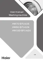
Remove the shipping boards from the bottom of the
vender. The shipping boards are attached by the
leveling legs. To avoid unnecessary damage to the
leveling legs or base, remove the shipping boards by
using a 1-1/2 inch socket type wrench to unscrew the
leveling legs. Be sure to replace the legs after
removing the shipping boards.
Once the vender is unpacked, check the recovery unit
for any additional parts, price/ product labels,
service/operation manual or other information
concerning factory-equipped accessories such as coin
mech and validator.
WARNING
: TO AVOID THE
POSSIBILITY OF A FIRE
HAZARD, DO NOT STORE
ANYTHING OR ALLOW DEBRIS
OF ANY KIND TO ACCUMULATE
IN THE BOTTOM OF THE
SERVICE AREA, IN AND
AROUND THE REFRIGERATION
COMPARTMENT OF THE
CABINET, OR IN FRONT OF
THE EVAPORATOR AND
CONDENSER COILS.
WARNING: ENSURE THAT
POWER IS DISCONNECTED
FROM THE VENDER OR
THAT THE POWER
INTERRUPT SWITCH IS NOT
DEFEATED BEFORE
INSPECTING OR REPLACING
THE LAMPS, OTHER
ELECTRICAL COMPONENTS,
OR WORKING WITH OR
ADJUSTING THE VENDING
MECHANISM. FAILURE TO
COMPLY WITH THESE
INSTRUCTIONS MAY SUBJECT
THE USER TO THE RISK OF
ELECTRICAL SHOCK OR
MECHANICAL INJURY, WHICH
CAN BE SERIOUS OR FATAL.
ELECTRICAL POWER NEEDED
Refer to the cabinet serial number plate to determine
the proper voltage and frequency the machine
requires (domestically, this requirement is 120 Volts,
60 Hertz). The cabinet serial plate also indicates the
amperage of the vender. The vender must be
plugged into a properly rated, single phase alternating
current outlet with its own circuit protection
(fuse/circuit breaker).
DO NOT USE AN EXTENSION CORD.
GROUND THE VENDER
The vender is equipped with a three-wire power
supply cord and MUST be plugged into a properly
grounded outlet.
DO NOT REMOVE THE GROUND
PIN OR IN ANY WAY BYPASS,
MODIFY, DEFEAT, OR DESTROY
THE GROUNDING SYSTEM OF
THE VENDER.
If the outlet will not accept the power cord plug,
contact an electrician to install a proper AC outlet.
FAILURE TO COMPLY WITH
THESE INSTRUCTIONS MAY
SUBJECT THE USER TO THE RISK
OF INJURY OR ELECTRICAL
SHOCK WHICH CAN BE SERIOUS
OR FATAL. PERIODICALLY
INSPECT THE POWER SUPPLY
CORD FOR DAMAGE. IF THE
CORD BECOMES DAMAGED IT
MUST BE REPLACED WITH THE
SAME SIZE AND TYPE CORD.
CONTACT DIXIE-NARCO FOR
ASSISTANCE.
INSTALLATION AND SETUP
INSTRUCTIONS
Open the service door on the right side using the key
provided in the coin return cup, or if shipped with a
locking clip, remove the clip and install the lock.
Ensure there is no power to the AC Distribution Box.
On venders with a main power switch on the AC
Distribution Box the switch needs to be in the OFF
position. On venders with a main power quick
disconnect plug on the AC Distribution Box the quick
disconnect plug needs to be unplugged. Check that
all connectors are firmly seated on the control board
and at the various components on the service door
(coin mech, keypad, etc.).
Retrieve the main power plug from the hole in the rear
of the vender and plug the cord in a properly
grounded 120VAC, 15 Amp receptacle (U.S. and
Canada).
Open the service door and apply power to the AC
distribution Box (if equipped with a bill acceptor, the
acceptor should cycle twice). The display on the door
Summary of Contents for DN 2145
Page 1: ......
Page 40: ...40 DN55 VENDER NON ENERGY STAR Beverage Max Diagram 9 Column ...
Page 41: ...41 DN55 ENERGY STAR VENDER Beverage Max Diagram 9 Column ...
Page 42: ...42 DN35 VENDER NON ENERGY STAR Beverage Max Diagram 6 Column ...
Page 43: ...43 DN35 ENERGY STAR VENDER Beverage Max Diagram 6 Column ...
Page 44: ...44 DN55 35 Compressor Wiring Diagram ...
Page 45: ...45 DN55 DN2145 AC DISTRIBUTION BOX SCHEMATIC DOMESTIC NON ENERGY STAR FIGURE 3 ...
Page 46: ...46 DN55 2145 AC DISTRIBUTION BOX SCHEMATIC EXPORT FIGURE 4 ...
Page 47: ...47 DN35 AC DISTRIBUTION BOX SCHEMATIC DOMESTIC NON ENERGY STAR FIGURE 5 ...
Page 48: ...48 DN55 35 AC DISTRIBUTION BOX SCHEMATIC DOMESTIC ENERGY STAR FIGURE 6 ...
Page 50: ...50 ECC SYSTEM SCHEMATIC RIGHT SIDE MDB SAMPLE ...
Page 51: ...51 ECC SYSTEM SCHEMATIC LEFT SIDE SAMPLE ...
Page 52: ...52 ASSY AC BOX DOMESTIC ...
Page 53: ...53 ASSY AC BOX DOMESTIC T8 Electronic ...
Page 54: ...54 ASSY AC BOX CE GS EXPORT ...
Page 56: ...56 MACHINE FRONT VIEW 1 14 6 7 3 5 2 4A 4B 4C 13 10 11 15 8 ...
Page 58: ...58 MACHINE FRONT VIEW 2 7 14 3 13 2 1E 1C 11 1B 6 10 11 1G 4 17 ...
Page 60: ...60 CABINET DETAIL 14 3 9 12 3 1 2 7 8 8B 7 10 11 11 13 5 6 ...
Page 64: ...64 SERVICE DOOR 1 1 5 6 7 8 6F 6J 3 6A 7 ...
Page 66: ...66 SERVICE DOOR 2 15 6 5 4 1 2 6 17 20 8 19 21 9 11 12 4 14 18 ...
Page 68: ...68 SERVICE DOOR 3 12 17 2 20 7 5 13 19 14 15 11 4 10 9 8 ...
Page 70: ...70 TALL GATE TRAY DETAIL 1 8 9 8 13 15 15 14A 14C 14B 18 16 14B 12 ...
Page 75: ...75 EXPORT AC DISTRIBUTION BOX 220 VAC 4 ...
Page 77: ...77 REFRIGERATION UNIT DN 55 35 FIN TUBE CONDENSER 19 11 10 13 18 9 1 22 15 13 16 6 5 2 8 17 ...
Page 79: ...79 REFRIGERATION UNIT TECUMSEH DN 5500 DN 5400 DN 2145 ROLL UP CONDENSER ...
Page 82: ...82 HARNESSES 1 2 3 7 4A 6 4B 24 22 5A 5B 5C 9 10A ...
Page 85: ...85 SCREWS NUTS ...