78
Network Guide
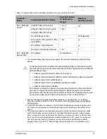
A controller can support a maximum of two (2) Allure Series sensor models equipped with a
CO2 sensor; the remaining connected models must be without a CO
2
sensor. See
work Module Compatibility and Supported Quantity Charts
on page 71 for the quantity of room
devices supported by each controller model.
For instance, if the subnetwork for the controller model supports a subnetwork with 12 Allure
Series sensors in total, then 10 Allure Series sensor models must be without a CO2 sensor
and the remaining two (2) Allure Series sensor models can be equipped with a CO2 sensor.
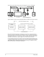
To ensure proper operation, it is recommended to distribute the sensors throughout the length
of the subnetwork.
Figure 49: Allure Series Sensors Subnetwork Length and Distribution
ECx-400 Subnetwork Bus
Cat 5e Cable with RJ-45 Connectors
Typical ECB/ECL-600 Controller
EC-Smart-Vue Subnetwork
Subnetwork Bus Total Length: 1 000 ft (300 m) Maximum
10x...
2x...
Bus: 600 ft (180 m) Maximum
Typical ECB−600 /
ECL−600 Controller
Summary of Contents for ECB-VAV
Page 1: ...User Guide Network Guide...
Page 6: ...Table of Contents 4 Network Guide...
Page 52: ...50 Network Guide...
Page 70: ...68 Network Guide...
Page 110: ...108 Network Guide...
Page 121: ...LonWorks Troubleshooting Network Guide 119...
Page 122: ...120 Network Guide...
Page 124: ...122 Network Guide...
Page 128: ...126 Network Guide...
Page 136: ...134 Network Guide...
Page 137: ...Network Guide...
Page 138: ...Network Guide_UG_24_EN...


