background image

49

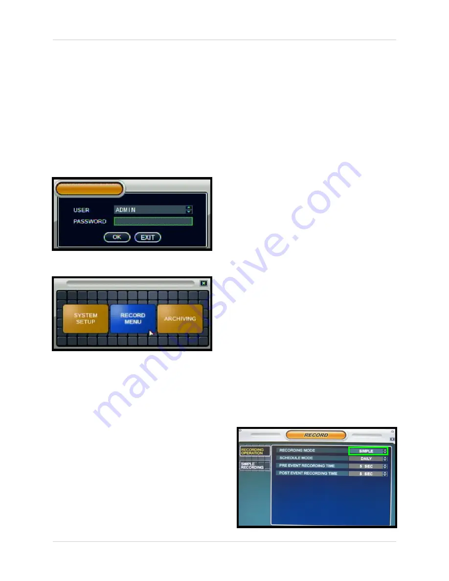
Recording Menu Controls

Recording Menu Controls

• Enter the 

RECORDING


MENU

 screen 

by: 

z

Pressing the 

SETUP 

button on the 

Remote Control

z

Pressing the 

SETUP

 button on the front 

panel, or 

z

Selecting the 

SETUP 

option from the 

On-Screen Menu. 

Enter the password if required using 
the Virtual Keyboard.

• Select the 

RECORD MENU

 option. 

• To enter a sub-menu, navigate to the 

option and press the 

ENTER

 button. To 

exit a 

SUBMENU

, press the 

RETURN

button. 

• To exit the 

MAIN MENU

, press the 

RETURN

 button.

NOTE

: When configuring the Recording 

Settings, it is recommended that you use the 
Mouse or Remote Control for navigation.


Alternatively, you can use the Client 
Software provided with this system to 
change the System Settings and Recording 
Configurations remotely. Please refer to the 
Client Software Manual for details.

Simple and Advanced Modes

This System allows you to configure the 
Recording Options in two ways:

• 

Simple Recording

: Simple recording 

will set all cameras to behave in the 
same way, with the same resolution and 
FPS. In Simple Recording, the 
recording type can be set to 

either

Continuous, Motion, Alarm or None.

• 

Advanced Recording

: Advanced 

recording will allow you to configure 
each camera to behave in a different 
way, based on quality, FPS and 
resolution. In Advanced Recording, the 
menus are separated so that you can 
set each camera to record in 
Continuous, Motion and Alarm at the 
same time.

For example, set the system to record 
in Continuous, Motion and Alarm at the 
same time. A camera will be in 
continuous recording, however when a 
Motion or Alarm event is detected, the 
onscreen indicator will switch to M or 
A, and the event will be logged in the 
system. 

To switch between Recording Modes, 
change the Recording Mode setting on the 

RECORDING OPERATION

 tab to either 

Simple or Advanced.

Summary of Contents for D2216 Series

Page 1: ...merge Technologies Inc Professional Integrated Surveillance System 22 LCD Monitor with Integrated 16 Channel Digital Video Recorder Multi Function Display Installation User Manual English Version 1 0...

Page 2: ...ATCH WIDE BLADE OF PLUG TO WIDE SLOT FULLY INSERT Thank you for purchasing the LCD 16 Channel Integrated DVR Digimerge is committed to providing our customers with a high quality reliable security pro...

Page 3: ...ord and if its appearance indicates damage or deteriorated insulation have it replaced by your service technician 7 Power Cord Protection Power supply cords should be routed so that they are not likel...

Page 4: ...can prevent fire electric shock or other hazards 15 Safety Check Upon completion of any service or repairs to this video product ask the service technician to perform safety checks recommended by the...

Page 5: ...z Consult the dealer or an experienced radio or television technician for assistance DIGIMERGE TECHNOLOGIES INC http www digimerge com NOTE This equipment has been certified and found to comply with...

Page 6: ...l Video Compression small file sizes without compromising video quality Recording Frames Per Second FPS 240 200 NTSC PAL 352X240 Recording Resolution 704x480 704x240 352x240 NTSC 704x576 704x288 352x2...

Page 7: ...rder DVR Mode Mode 1 21 DVR Mode Remote Control Usage 22 Front Panel Navigation Controls 23 Mouse Control 23 On Screen Display Menu 24 System Display 25 Menu Navigation Controls Tips 26 System Setup C...

Page 8: ...g up Remote Viewing Appendix 3 76 Using the Auto Email Feature Appendix 4 88 Recommended Tips for System Setup Appendix 5 92 Listen in Audio Appendix 6 99 Playback Of Previously Recorded Data Appendix...

Page 9: ...EASE REFER TO YOUR PACKAGE FOR CONTENT DETAILS CHECK YOUR PACKAGE TO CONFIRM THAT YOU HAVE RECEIVED THE COMPLETE SYSTEM INCLUDING ALL COMPONENTS SHOWN ABOVE REMOTE CONTROL ETHERNET CABLE POWER ADAPTER...

Page 10: ...r Remote Access it is very important to turn off the System CONNECT THE ETHERNET CABLE to the system and to the Router and then turn the System back on again If the cable is connected while the System...

Page 11: ...using the HARD DRIVE VIEWER software included on the CD provided with this unit Please see the Appendices for details on Hard Drive format Monitor Display Shutoff Press the Power Button on the front p...

Page 12: ...cted to the component green blue and red inputs Y Pb Pr in high resolution i e DVD Player Picture Frame Mode Displays jpg images from a USB Thumbstick on the monitor as still images Images cannot exce...

Page 13: ...at a remote connection has been made to the unit over the Network when the RED LED is ON Side Panel USB Ports The USB Ports provide a connection point for a USB PC Mouse USB Flash Drives thumbsticks a...

Page 14: ...form as a Computer Monitor when in VGA Mode 5 COMPONENT VIDEO IN Connect a DVD Player Set Top Box or Satellite Receiver to the component Video Inputs Y Pb Pr 6 COMPONENT AUDIO IN Connect a DVD Player...

Page 15: ...ve the system in a back room while still displaying images to the public eye for theft deterrence or advertising purposes 12 AUDIO OUT Audio Output port to connect the unit to a secondary audio device...

Page 16: ...to the system 1 Connect the cable to the Input located on the back of the System 2 Attach BNC Type cameras to the cables Each cable is labelled with a channel number Once the cable and cameras are att...

Page 17: ...amera in a location that has conditions not recommended in this manual consult with a professional installer and consider use of a separate camera cover or housing Before starting permanent installati...

Page 18: ...nect the Power Adaptor to a wall outlet IMPORTANT NOTE The ends of the extension cable are NOT the same one end has a Male power port and the other has a Female power port Before permanently running t...

Page 19: ...ted together when connecting the cable If the pins in the DIN Cable are bent the Camera will NOT function 2 Connect the male end of the supplied DIN extension cable to an open DIN camera input on the...

Page 20: ...the device connected to the component green blue and red inputs Y Pb Pr in high resolution i e DVD Player Set Top Box or Satellite Receiver Mode 4 Picture Frame Mode Displays jpg images from a USB Th...

Page 21: ...e through FTP Search through Previously Recorded Events Customize the Display Cameras and System to best suit your security needs through the user friendly System Menu GUI Graphical User Interface NOT...

Page 22: ...NUMBER KEYPAD Use to switch between Cameras in live view mode 10 VOL Increase or Decrease the volume of the camera currently broadcasting live audio 11 DVR SETUP Displays the DVR Setup Menu 12 REMOTE...

Page 23: ...es in a menu option Mouse Control This System has been designed to use the Mouse or Remote Control as the primary modes of navigation and configuration for the system Connect a mouse to one of the USB...

Page 24: ...een views 6 ARCHIVE The Archive feature copies data from the Hard Drive to a USB backup media such as a Memory Stick or USB Hard Drive See the Archive Menu Section for details 7 SEQUENCE Selecting the...

Page 25: ...for the camera is displayed in the upper left corner of the channel window to a maximum of 11 characters To change the name use the System Setup options Date Time Displays the current Date and Time fo...

Page 26: ...Camera in ZOOM Mode Use the Arrow keys to adjust the Zoom location Press the Return key to exit ZOOM Mode Quad 4 Channel 6 Channel Split View 8 Channel Grid Cameras can be displayed in several differe...

Page 27: ...mote Control or Mouse Menu to access the PTZ Control Screen The onscreen icons represent buttons on the front panel and remote control up down left right The Camera can be adjusted using these buttons...

Page 28: ...e Adjustment Displays the volume level of the Camera currently set to Live Audio The Camera Volume can be controlled using the Volume keys NOTE Once changes have been made select the APPLY button at t...

Page 29: ...ront Panel or Remote Control or clicking with the Mouse To enter a sub menu navigate to the option and press the ENTER button To exit a SUBMENU press the RETURN button To exit the MAIN MENU press the...

Page 30: ...splay motion sensor except motion detection area z Off No display of motion sensor Motion Sensor Color Sets the motion sensor color When Motion is detected on a channel the moving parts of the image w...

Page 31: ...and moves to the New Sequence Configuration screen MONITOR Sequence Dwell Sets the cycle time when the system is in Sequence Mode between 1 60 seconds Spot Out Dwell The length of time to display a ca...

Page 32: ...the MODIFY button to configure the views then press the SAVE Button 1 Press the ENTER button on the Remote The Highlight will change to YELLOW Setup Mode is now active SEQUENCE SETUP REMOTE 2 Select t...

Page 33: ...e Highlight will change to YELLOW Setup Mode is now active SEQUENCE SETUP MOUSE 2 Select the Display Mode by single left clicking to switch 5 different Display Options Single Quad 6 split 8 split 8 qu...

Page 34: ...Main Display Screen ON OFF z ON The Main Display is always ON z OFF The Main Display is always OFF FROM Used ONLY when the Main Display OFF setting is set to ON Sets the Start Time for the monitor to...

Page 35: ...ividual camera 0 9 A Z up to 11 characters by using the Virtual Keyboard z Virtual Keyboard Appears when the Camera Title change is selected Navigate with the arrow keys and press ENTER to select a Nu...

Page 36: ...cameras Press the ENTER Button and select a camera setting Set the Brightness Contrast Tint and Color for each camera These settings can be set to a range of 1 low 100 high Press the RETURN button to...

Page 37: ...omatic Shutter to ON OFF Speed Controls Sets the Pitch Zoom Focus and Iris speeds between 1 5 MOTION SENSOR AREA SETUP Move the Cursor by using the directional arrows located on the Remote Control or...

Page 38: ...Audio Turns Live System Audio from the Audio on the terminal to ON OFF Audio Monitoring Channel Select the channel for Listen in Audio Channels 1 4 ONLY NOTE Listen In Audio only works with Channels...

Page 39: ...reached a Failure to Connect message appears Timezone Setup Selections for the local Time Zone i e EST CST PST The DST Daylight Savings Time can be set to ON OFF NOTE MAKE SURE THAT THE DATE AND TIME...

Page 40: ...te z Refer to the Network Setup instructions in the Appendices for information on using the Free DDNS Service Web Service Allows the unit to be remotely accessed using Internet Explorer This setting c...

Page 41: ...ration and generates a SUCCESS or FAIL message USER MANAGEMENT USER MANAGEMENT The User setup consists of 3 groups Administrator Manager or User Up to 7 new users can be added to the system A maximum...

Page 42: ...ilable for download from the www digimerge com website SYSTEM MANAGEMENT System Information Navigate to the PRESS button and choose ENTER to display the System Information To display the System Inform...

Page 43: ...on performing a Remote Firmware Upgrade The firmware on the unit can be updated via the USB Port Download the new firmware from the website Copy the files from the PC to the USB Memory Stick Insert t...

Page 44: ...Control ID to match the system ID Protocol Select protocol from the Device user Manual Baudrate Setup baudrate from the Device user Manual Factory Defaults The System can be returned to the Factory d...

Page 45: ...s Enable Disable for an external alarm i e Door or Window Sensors Refer to the appendices for details Type Sets the Alarm Sensor type to N O Normally Open or N C Normally Closed Event Sensor The Event...

Page 46: ...experiencing problems CH1 16 Alarm Sends the Alarm Out when an Alarm Event is detected set to ON OFF CH 1 16 Video Loss Sends the Alarm Out when a Video Loss Event is detected set to ON OFF CH 1 16 M...

Page 47: ...drive For example The Record Time Limit is set to 1 week The System records data from the 1st of the month through the 7th of the month On the 8th of the month it will begin overwriting data hour by h...

Page 48: ...CEL to return without erasing the Hard Drive Once OK is selected the user will be prompted to enter the ADMIN PASSWORD Once the password is accepted all Hard Drive data will be erased NOTE After Forma...

Page 49: ...l for details Simple and Advanced Modes This System allows you to configure the Recording Options in two ways Simple Recording Simple recording will set all cameras to behave in the same way with the...

Page 50: ...mode Simple Recording The Simple Recording Menu controls the Quality Size and FPS for all cameras at the same time Each channel can be set for a single Recording Type Continuous Motion Alarm or None...

Page 51: ...Alarm Recording Once a selection has been made the Recording Selection window will close Advanced Recording Recording Operation The Recording Operation Menu allows the user to switch between Simple an...

Page 52: ...otion Parameter Select an Hour highlighted in ORANGE and press ENTER again to open the Camera Settings for the selected hour or select multiple blocks in a row and press ENTER Once a time block or sev...

Page 53: ...the ENTER key Once the desired time s have been selected the Recording Setting menu is displayed Select from NONE Recording is turned OFF CONTINUOUS Recording is always ON MOTION Only starts the recor...

Page 54: ...ANGE and press ENTER again to open the Camera Settings for the selected hour or select multiple blocks in a row and press ENTER Once a time block or several blocks have been selected the Channel Setup...

Page 55: ...nnel 1 will be highlighted in Yellow z Navigate to the desired time block and press the ENTER button to activate the block if a single block is desired press ENTER a second time z To select multiple b...

Page 56: ...NU press the RETURN button To exit the MAIN MENU press the RETURN button Archiving Options Select Device Displays all detected backup media devices USB Flash Memory Stick or USB Hard Drive or allows t...

Page 57: ...MB and Size of the Log File Select OK to begin the backup The Writing status window displays the completion state of the Backup in The Extracting status window displays the completion state of the Ext...

Page 58: ...he FTP site A Success or Fail message will appear Once a successful connection has been made the FTP Configuration Menu will be displayed Operation Set the FTP Backup to ON or OFF Device Set to FTP as...

Page 59: ...rd if required Use the Left Right arrows on the Remote Control or click with the mouse to switch between the Search By Time and Search By Event screens Search By Date Time Searches the system based on...

Page 60: ...d Cameras Navigate within the options using the Arrow Keys on the front panel or remote control Press the Enter button to select or deselect options Note Multiple event types can be selected Navigate...

Page 61: ...utton on the Remote Control NOTE Press the PIP button to display the DVR in the bottom right corner VGA Connection Errors If the Computer is not correctly connected to the Monitor several different er...

Page 62: ...for 3 seconds to shut down the entire system 3 DVR MODE Return to DVR Mode 4 VGA MODE Change to VGA Mode 5 RETURN Exits from a System Menu 6 NAVIGATION Press the Navigation Controls to move Up Down L...

Page 63: ...onitor to Component Mode using the Multi Function Mode button on the front of the Monitor or by pressing the Component Button on the Remote Control NOTE Press the PIP button to display the DVR in the...

Page 64: ...em 3 DVR MODE Change to return to DVR Mode 4 VGA MODE Change to VGA Mode 5 RETURN Exits from a System Menu 6 NAVIGATION Press the Navigation Controls to move Up Down Left or Right in the Monitor Menu...

Page 65: ...ay the images USB Thumbstick Images Images must be in a jpg file format All other files will not be recognized by the Monitor including other Image formats i e BMP GIF or other file types i e in the e...

Page 66: ...ire system 3 DVR MODE Change to DVR Mode 4 VGA MODE Change to VGA Mode 5 RETURN Exits from a Menu 6 NAVIGATION Press the Navigation Controls to move Up Down Left or Right in the Monitor Menu 7 PICTURE...

Page 67: ...the PREVIEW button to display the images on the thumbstick in a Preview Pane Use the Navigation Controls on the front panel or Remote Control or use the mouse to select an image Click Previous or Next...

Page 68: ...Picture Resize window will be displayed 2 Click on the Source button to locate the directory where the JPG files are located Select a file and click on the Open button 3 Click on the Target button to...

Page 69: ...key on the remote control or front panel of the System to enter the Monitor Setup Menu when in VGA or Component Modes The Monitor Setup Menu controls the behavior and look of the Monitor i e changing...

Page 70: ...monitor Select YES to allow the system to set the color or NO to exit Phase Set the phase for the system Clock Set the internal clock for the System Display Control Submenu Display Image Sets the imag...

Page 71: ...t be displayed when the PIP button on the remote control is pressed PIP Input Select Select the input type for the PIP By default the unit will display the DVR screen PIP Size Change the display size...

Page 72: ...xit the menu OSD Timer Set the OSD Timer ON or OFF If the timer is set to ON the menu will automatically disappear after 30 seconds OSD Position Determines the position of the Onscreen Display window...

Page 73: ...iple control options front panel buttons remote control and mouse Tri lingual On Screen Display English Spanish French Screen saver for energy efficiency Wall mountable VESA standard Stand with cable...

Page 74: ...ivities leading up to an event Hard Drive with SATA interface 100 duty cycle for optimal performance in the commercial video security market Expandable up to 750GB4 S M A R THDD Support Self Monitorin...

Page 75: ...umer guides Operating System Windows 2000 Windows XP Home Edition Windows XP Professional Windows Vista 32 bit Processor Pentium 4 1 5 GHz Processor or equivalent Memory 512 MB RAM Hard Drive 50 MB In...

Page 76: ...rolled using your existing network and the DigiClient 8 0 soft ware or Internet Explorer 1 Connect the System to the Router using the supplied Ethernet Cable Power the System on The System must be con...

Page 77: ...the SETUP option Select the System Setup option Select the System option Select the Network Menu Confirm that the options for both DHCP and DDNS have checkmarks in the boxes 3 I have turned off the S...

Page 78: ...rk settings Press the SETUP button on the Front Panel or Press SETUP on the Remote or Right Click on the screen and select the SETUP option Select the System Setup option Select the System option Sele...

Page 79: ...p Menu Select the System Setup option and press the Enter button 2 Navigate to the System Menu option Press the Enter button to access the System Menu 3 Navigate to the System Management menu and pres...

Page 80: ...rding tells the router which device on the internal network to send the data to When you set up port forwarding on your Router it takes the data from the external IP address port number and sends that...

Page 81: ...DNS digimerge net 2 Select the Create Account option from the list on the left side of the screen 3 Complete the Account Information fields with your personal information 4 Complete the System Informa...

Page 82: ...for remote access to your System Record YOUR information below Domain ________________________________________________________ User ID __________________________________________________________ User P...

Page 83: ...DOMAIN NAME cats USER ID aa321 USER PASSWORD 1111 DDNS STATUS OK CANCEL Press DDNS STATUS button and wait for the message SUCCESS If the message returns SUCCESS press OK and press the return button t...

Page 84: ...o access the setup 2 Navigate to the NETWORK option Press the Enter button to access the Network settings Select the DDNS Server option and press the ENTER button to enter the DDNS SETUP 3 Enter the i...

Page 85: ...allow the user to remotely connect to the System Adding a Group Group Right click on Site to add a New Group A group can represent one or more Systems For Example you may have more than one system in...

Page 86: ...tem i e ADMIN case sensitive Password The password used to access the System i e The ADMIN password is set to 1234 by default Camera Assign Set each camera to a portion of the 9 view window by using t...

Page 87: ...Select the Site profile from the Dropdown List 2 Press the CONNECT button The Connection Status window displays the state of the connection Once a successful connection to the System has been made the...

Page 88: ...re these settings Configuration using the Digimerge Mail Server Make sure the box is checked and you will not need to enter any additional information however YOU WILL BE REQUIRED to set up your syste...

Page 89: ...trate the required settings using another program Testing the Mail Setup Press the TEST E MAIL Button on the System A window will appear indicating a Success or Fail for the connection Test Results in...

Page 90: ...ification Set the E Mail to the desired Receiving Address Set the E Mail Notification to ON This must be set ON for the user to receive mail Troubleshooting the Email Feature If you are having problem...

Page 91: ...ification Alarm Video Loss or Motion Detection for each channel FREQUENCY Set the frequency to receive mails for the duration of the event NOTE The Notification Email will only alert you to the fact t...

Page 92: ...e options by pressing the UP DOWN LEFT and RIGHT buttons on the Front Panel or Remote Control To enter a sub menu navigate to the option and press the ENTER button To exit a SUBMENU press the RETURN b...

Page 93: ...button once the setup is completed Active Option Indicator NOTE Once changes have been made select the APPLY button at the bottom of the screen and press the ENTER button on the front panel or remote...

Page 94: ...by navigating with the UP DOWN LEFT and RIGHT arrow keys Setthefollowingbasedonyourlocal Time and Timezone and set the current date for the system Date Time Sets the current system Date and Time Date...

Page 95: ...ect the SYSTEM SETUP Option 2 Select the DISK MANAGEMENT menu from the MAIN menu Navigate using the up and down arrows on the front panel or remote control Highlight the selection in Green and press t...

Page 96: ...the settings by navigating with the UP DOWN LEFT and RIGHT arrow keys CAM Indicates the Camera Number corresponds to the DIN BNC connection port on the back of the system Covert Turns the onscreen di...

Page 97: ...SCREENSAVER Menu Change the settings by navigating with the UP DOWN LEFT and RIGHT arrow keys Set the screen saver options Auto Brightness Sets the length of time before the Screen brightness is turn...

Page 98: ...ght the selection in Green and press the ENTER button to enter the SYSTEM MANAGEMENT Menu 3 Navigate to the System Data option the System settings can be saved to a USB memory stick Insert the Memory...

Page 99: ...m or on the Remote Control Select the SYSTEM SETUP Option 2 Select the SOUND menu from the MAIN menu Navigate using the up and down arrows on the front panel or remote control Highlight the selection...

Page 100: ...or Remote Control to switch between the Search By Time and Search By Event screens Search By Time Searches the system based on date and time Press the Enter button to access the Calendar on the left...

Page 101: ...uous Motion and Other and Cameras Navigate within the options using the Arrow Keys on the front panel or remote control Press the Enter button to select or deselect options Note Multiple event types c...

Page 102: ...n the front panel of the system Remote Control or mouse menu Select the RECORD MENU Option 2 Select the SIMPLE RECORDING MODE menu Navigate using the up and down arrows on the front panel or remote co...

Page 103: ...control Navigate using the arrow keys 3 Select the Channel Menu 4 Press the ENTER key to enter the configuration mode One time block will be highlighted in LIGHT BLUE 5 Navigate to the desired time bl...

Page 104: ...dual cameras on one time block or can be set for multiple cameras for multiple time blocks 1 Press the Setup button on the front panel of the unit or Press the Setup button on the Remote Control or Ri...

Page 105: ...it will change to a red box with a yellow M Continuous Motion This system has an Advanced Recording Feature where BOTH Continuous and Motion can be set to ON at the same time The system will record c...

Page 106: ...areas which you do not want to have detect motion such as a heavy traffic area or a piece of machinery which is in continuous motion To change the Motion Detection Area Select the SYSTEM SETUP option...

Page 107: ...g Resolution to CIF 352x240 2CIF 704x240 or D1 704x480 Quality Set the recording Quality to Low Standard High or Highest FPS Set the Frames Per Second for the recording to 1 2 4 8 15 or 30 FPS AUDIO S...

Page 108: ...ith your product Lorex recommends Seagate SV35 Series Hard Disc Drives which support 100 duty cycle providing the reliability required for video surveillance applications Setting the New Drive to Mast...

Page 109: ...tted If a new HARD DRIVE is detected the system will prompt you to FORMAT the drive If you do not choose to format the HARD DRIVE the drive will not be detected by the system If you choose to FORMAT a...

Page 110: ...UT Displays Cameras in Sequence mode regardless of the display on the DVR i e Camera Views Menus Playback etc to a TV or VCR Configure the Spot Out settings using the System Menu controls when in DVR...

Page 111: ...Menu Example A Window sensor unit has been installed on Alarm Block port 4 When this sensor is activated the camera on DIN or BNC VIDEO port 4 will become active if enabled in the MENU on the System...

Page 112: ...he D port on the PTZ Control Block on the System 3 Connect the Camera to a BNC Channel 4 Configure PTZ Menu options The PTZ Camera Settings will depend on the Type of Camera refer to the specific Came...

Page 113: ...outlines a general set of connections available with the System SYSTEM SENSOR Not Included PC for Remote Access Not Included ROUTER Not Included SLAVE SPOT OUT MONITOR Not Included BNC CAMERAS CH1 8...

Page 114: ...aired or replaced with equal or better product in terms of hardware features without charge if all the conditions set forth in this warranty are met Any products repaired or replaced within the warran...

Page 115: ...ot allow the exclusion or limitation of implied warranties or the limitation of incidental or consequential damages for certain products supplied to consumers or the limitation of liability for person...

Page 116: ...It s all on the web Product Information User Manuals Quick Start Guides Specification Sheets Software Upgrades Firmware Upgrades Digimerge Technologies Inc VISIT www digimerge com www digimerge com...

Reviews: