


Chapter 10: Monitor and Meter Sections
91
Listen Control
The Listen system has two selectable microphone inputs, both
using the touch-sensitive rotary encoder for level control.
Listen Mic Select Switches
There are two Listen Mic Select switches for the external listen
microphone inputs:
• Mic 1
• Mic 2
Either or both of these inputs can be active at any time. When
one input is active, the encoder controls the level of that input
independently. When both inputs are active, the encoder con-
trols both levels simultaneously, maintaining any relative off-
set between the two.
Level control ranges from a minimum level of –INF to a max-
imum level of +30 dB.
Dim Level Control
The Dim Level control lets you adjust the amount of level re-
duction applied by the Dim switch, located at the bottom of
the Monitor section. Level reduction ranges from –30 dB to
0 dB, in 1 dB steps.
When the Dim encoder knob is touched, the monitor section
display shows “Dim” and the gain reduction in dB.
Monitor Output Mode Controls
Calibration Mode Switch
The Calibration Mode switch invokes a mode that changes the
output value displayed by the Monitor section display from
gain
(expressed in dB) to
sound pressure level
(expressed in
dB SPL) for each of the control room outputs. This switch
lights when an SPL value is shown for the active output.
To display output levels in dB SPL, you must first calibrate
each output. This SPL calibration requires the use of a pink
noise source (or other reference material) and a sound pressure
level meter to measure the output of individual control room
speakers.
To calibrate Control Room outputs to display SPL:
1
Send the reference material to the Main Control Room Out-
puts, and set the output level in Pro Tools to your studio ref-
erence level (for example, –18 dBFS).
2
Pan the signal to center (so that equal level is sent to all
Main Control Room Output speakers).
3
Set the speaker-to-speaker balance for all speakers in the sys-
tem using Output Trim mode for each channel, using the
sound pressure level meter to measure SPL at the mix position.
See “Individual Output Trim Mode” on page 88.
4
Solo the Center speaker, and adjust the Main Control Room
Output level encoder until the sound pressure level meter
measures the target reference level (for example, 85 dB) at the
mix position.
5
Press and hold the Calibration Mode switch until it flashes.
6
Adjust the Main Control Room Output level encoder until
the target reference level is displayed in the Monitor Section
display.
7
Press the flashing Cal switch.
8
Repeat steps 4–7 for the Alt and Mini outputs.
To toggle the output display between dB and dB SPL:
1
Select the output whose display you want to toggle (Main,
Alt, or Mini).
2
Press the Calibration Mode switch.
When the Calibration Mode switch is lit, output is displayed
in dB SPL.
When the Calibration Mode switch is unlit, output is dis-
played in dB.
Mono Switch
The Mono switch mixes the Left and Right signals of any of
the output modes (any surround channels are not affected) to
provide mono output, useful for checking phase and balance
relationships. The Mono switch lights to indicate that it is ac-
tive.
Mono Trim Mode
Mono output can be trimmed to adjust its reference level in
comparison to other outputs. Available trim values range from
–12 dB to 0 dB, in 0.5 dB steps.
To trim mono output:
1
Press and hold the Mono switch until it flashes.
2
Turn Alt Output encoder knob to set the Mono trim value.
The monitor display shows “Trim” and the trim value in dB.
3
Press the flashing Mono switch to exit Trim mode.
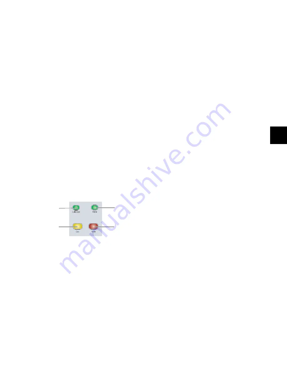
Monitor Output Mode controls
Calibration Mode
switch
Dim switch
Mono switch
Mute switch
Summary of Contents for D-Command
Page 1: ...D Command Version 7 3 ...
Page 4: ......
Page 7: ...Part I Introduction ...
Page 8: ......
Page 19: ...Part II Installation ...
Page 20: ......
Page 35: ...Part III Reference ...
Page 36: ......
Page 72: ...D Command Guide 66 ...
Page 90: ...D Command Guide 84 ...
Page 124: ...D Command Guide 118 ...
Page 128: ...D Command Guide 122 ...
Page 134: ...D Command Guide 128 ...
Page 135: ......


