DigiDesign D-Command Manual Download Page 17

Chapter 2: D-Command Overview

11

D-Command XMON Interface

D-Command monitoring is based on the XMON analog interface, which is remotely controlled from the D-Command 
monitoring section.

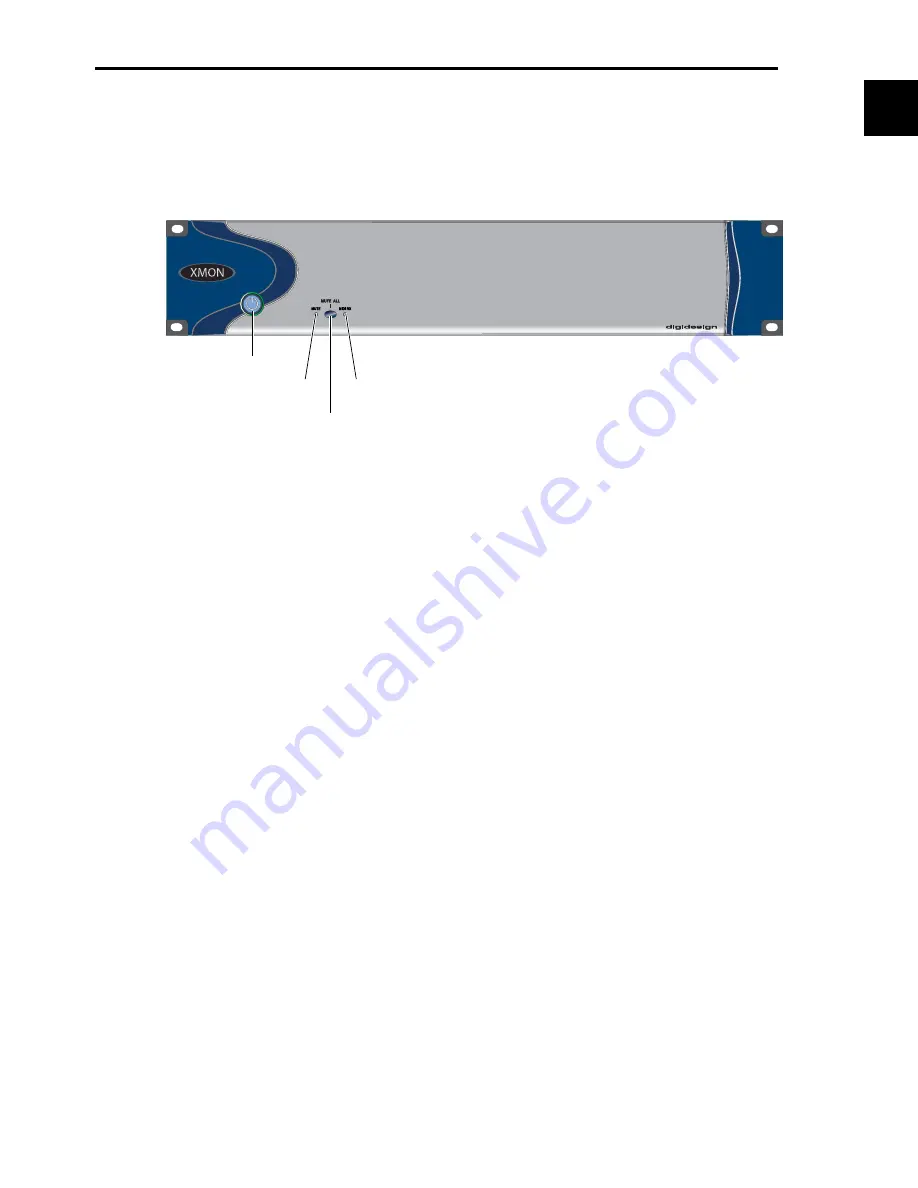
XMON Front Panel

Power Switch

The Power switch applies power to the XMON Interface.

Mute Indicator

The Mute indicator shows the mute status of XMON. 

MIDI Receive Indicator 

The MIDI Receive indicator shows MIDI activity between 
XMON and D-Command. 

Mute Button

The Mute button mutes all XMON outputs. It is not possible 
to unmute XMON with this button. The XMON mute state 
can only be cleared from the D-Command Monitor section 
(see “Monitor Section Controls” on page 85).

Figure 4.  XMON front panel

Power
switch

MIDI Receive
indicator

Mute
indicator

Mute button

Summary of Contents for D-Command

Page 1: ...D Command Version 7 3 ...

Page 2: ... and Television Interference This equipment has been tested and found to comply with the limits for a Class A digital device pursuant to Part 15 of the FCC Rules Communications Statement This equipment has been tested to comply with the limits for a Class A digital device Changes or modifications to this product not authorized by Digidesign Inc could void the Certification and negate your authorit...

Page 3: ...L WARNING REGARDING VENTILATION Do not install D Command anywhere or in any way that blocks free air flow at any time around the back panel of the unit SPECIAL WARNING REGARDING AMBIENT TEMPERATURE Before powering on the D Command unit be sure to allow it to reach room temperature The unit includes some components that are senstive to cold temperatures so it is recommended that you unpack the unit...

Page 4: ......

Page 5: ...D Command Fader Module 10 D Command XMON Interface 11 Part II Installation Chapter 3 Setting Up the Fader Module 15 Assembling an Expanded System 15 Chapter 4 Connecting D Command 17 D Command Connections 17 Audio Connections 19 Chapter 5 Configuring D Command 23 Starting Up and Shutting Down the System 23 Software Configuration 23 Setting D Command Preferences 24 System Calibration 28 Part III Re...

Page 6: ...itor Section Controls 85 Meter and Time Code Displays Main Unit 93 Setting D Command Meters for Different Reference Levels 94 Chapter 11 Operating Modes 95 Normal Mode 95 Custom Fader Modes 100 Working with Automation 107 Appendix A Utility Mode 111 Entering Utility Mode 111 Navigating Utility Mode 111 Exiting Utility Mode 112 D Command System Info Page 112 D Command Name Page 112 D Command Test P...

Page 7: ...Part I Introduction ...

Page 8: ......

Page 9: ...ols including location commands and scrub shuttle capability Monitoring Features 6 channel control room monitoring system supports mono through 5 1 surround monitoring with up to 5 possible in put sources and 3 selectable output paths 2 channel cue system with 4 separate outputs and selectable talkback feed Built in talkback microphone and external talkback mic input Standalone mode for monitoring...

Page 10: ...source not included is highly recommended Ethernet Connections Each D Command unit communicates with Pro Tools using Ethernet A single Main Unit can be connected to the host computer without an Ethernet hub To connect multiple D Command units to the host computer an Ethernet hub not included is required Audio Connections All external analog audio inputs and outputs for control room monitoring and ...

Page 11: ...d 5 Mechanical Specifications D Command side dimensions 29 25 in 74 3 cm 14 4 in 36 6 cm 0 5 in 1 27 cm 2 55 in 6 48 cm 2 68 in 6 79 cm 4 24 in 10 78 cm 10 23 in 25 98 cm D Command top dimensions Main Unit 32 3 in 82 cm 29 25 in 74 3 cm ...

Page 12: ...D Command Guide 6 D Command top dimensions Main Unit and Fader Module 55 6 in 141 2 cm 29 25 in 74 3 cm ...

Page 13: ...controls Window Management section Session Management section Soft Keys section Nudge Bank section Zoom Navigation section Miscellaneous controls Talkback Microphone Main Time Scale display Automation Mode controls Dynamics Section EQ Section Transport Section Rotary Encoder section Meter section Channel Strip Display controls Channel Channel Strip Mode controls Modifier faders keys ...

Page 14: ...ections on the D Command Main Unit include controls for opening and closing Pro Tools windows and managing and saving Pro Tools sessions See Window Management Section on page 73 and Session Management Section on page 74 Soft Keys Section The Soft Keys section on the D Command Main Unit provides access to a wide range of Pro Tools commands directly from the control surface It also provides access t...

Page 15: ... a 1 4 inch TRS jack that supports two footswitch connections See Footswitch Connections on page 18 Ethernet Connector The Ethernet connector on the back panel of the D Command Main Unit provides communication to Pro Tools See Ether net Connections on page 17 XMON Monitoring System Connector The 15 pin connector on the back panel of the D Command Main Unit provides remote control of all audio moni...

Page 16: ...te the function of the Pro Tools computer keyboard modifiers See Modifier Key Switches on page 37 Fader Module Back Panel AC Power The AC Power connector accepts a standard AC power cable The D Command Fader Module is auto power selecting 100V to 240V and automatically works with a standard modular power cord when connected to an AC receptacle in any country Power Switch The Power switch applies p...

Page 17: ... Mute Indicator The Mute indicator shows the mute status of XMON MIDI Receive Indicator The MIDI Receive indicator shows MIDI activity between XMON and D Command Mute Button The Mute button mutes all XMON outputs It is not possible to unmute XMON with this button The XMON mute state can only be cleared from the D Command Monitor section see Monitor Section Controls on page 85 Figure 4 XMON front p...

Page 18: ...rs for all external analog audio inputs and outputs for D Command See Audio Connections on page 19 Figure 5 XMON back panel Cue Inputs Cue Outputs Main Inputs Surround Inputs Stereo Inputs Main Outputs Alt Outputs Talkback Meter Calibration Control Surface AC Power Listenback Utility Screws ...

Page 19: ...Part II Installation ...

Page 20: ......

Page 21: ...the brackets You will also need access to the rear of the unit to make cable connections The Fader Module is designed to be attached to the left of the D Command Main Unit Assembling an Expanded System The D Command Main Unit can be attached to the D Com mand Fader Module using the front middle and rear brack ets included with the D Command Fader Module Assembly Hardware The following hardware is ...

Page 22: ...efully slide the connected units forwards far enough to have complete access to the center bracket screw holes 9 Attach the center bracket using two 10 32 3 4 inch socket cap screws 10 Press the D Command units together If necessary use a ratcheting nylon strap to press the units together by running the strap around the two units Make sure the nylon strap does not contact any switches or encoders ...

Page 23: ...face con nect the included AC power cord the unit and to a power source Ethernet Connections Each D Command unit communicates with Pro Tools using Ethernet An Ethernet cable is included with each D Com mand unit If you are connecting only one D Command unit to your computer 1 Connect one end of the supplied Ethernet cable to the Ethernet port on the back panel of D Command 2 Connect the other end ...

Page 24: ...ted to an Ethernet network it will be available to be declared by any Pro Tools system on that network This lets you control different Pro Tools systems on the network with a single D Command console You can only control one Pro Tools system at a time Footswitch Connections You can connect two SPST single pole single throw foot switch units to the D Command Main Unit to control any of the followin...

Page 25: ...tem Connection D Command connects to XMON with a single 15 pin XMON cable A 50 foot 15 25 m cable is included with the D Command Main Unit The system supports up to an 80 foot 24 5 m cable To connect the XMON to D Command 1 Connect the included AC power cord to the back panel of the XMON and to a power source A surge protected power source is highly recommended 2 Connect one end of the included XM...

Page 26: ...m power Outputs Main Control Room Outputs 6 channels balanced or unbalanced 4 dBu Alt Control Room Outputs 6 channels balanced or unbalanced 4 dBu Mini Control Room Outputs 2 channels balanced or unbalanced 4 dBu Figure 7 Control room monitoring system block diagram AFL PFL Input 2 channels Main Input 6 channels Surround Input 6 channels Stereo 1 Input 2 channels Stereo 2 Input 2 channels Stereo 3...

Page 27: ... Cue 2 2 channels 4 dBu Headphone 2 channels to internal headphone jack Studio Loudspeaker 2 channels Talkback Slate Output 1 channel Figure 8 Headphone Cue system block diagram Main Monitor Input Cue 1 Input 2 channels Cue 2 Input 2 channels Internal Talkback Input External Talkback Input Talkback switch Talkback Assign Internal Talkback Level External Talkback Level Talkback Slate Out 1 channel ...

Page 28: ...Cue 1 5 6 Cue 2 1 L 2 Lc 3 C 4 Rc 5 R 6 Ls 7 Rs 8 LFE 1 L 2 Lc 3 C 4 Rc 5 R 6 Ls 7 Rs 8 LFE 1 Ext Talkback Mic Input 2 Listen Mic 1 Input 3 Listen Mic 2 Input 4 AFL Input 1 5 AFL Input 2 6 Mini Speaker Out 1 L 7 Mini Speaker Out 2 R 8 Talkback Slate Out To Cue System Amplifiers To Main Speakers To Alternate Speakers To Various Inputs and Outputs DB 25 to DB 25 connectors DB 25 to XLR snakes 192 I ...

Page 29: ...tware Configuration All D Command software is included when Pro Tools software is installed The Pro Tools software installer places the D Com mand Personality folder on the system drive Refer to the Getting Started Guide that came with your system for instructions on installing or updating Pro Tools software Updating System Firmware Each release of Pro Tools software includes the most current D Co...

Page 30: ...etting D Command Preferences This section describes the settings and preferences for D Com mand that are set directly from the control surface For details on preferences that are set from Pro Tools refer to the Pro Tools Reference Guide Fader and Switch Preferences The following settings and preferences affect operation of the faders and switches on D Command Fader Bank Justification The Bank Just...

Page 31: ... the number of channels to be used when displaying channels in the Custom Fader modes Options are 4 and 8 faders for a Main Unit and 4 8 16 and 24 faders for an expanded system You can choose settings for each of these sizes indicated by the prefix Min that use the minimum number of channels necessary so that the Custom Fader section dynamically re sizes to match the number of channels in the grou...

Page 32: ...ry to step through the Fixed Vel Sl velocity sensitive slow Vel Md velocity sensitive medium Vel Fa veloc ity sensitive Fast and Fine settings 3 Hold Control Windows or Command Mac and press the Operation switch to exit Encoder Order The Encoder Order preference determines whether inserts sends and pan controls will be displayed in order from top to bottom or bottom to top on D Command rotary en c...

Page 33: ...he Soft Key that corresponds to InsMtr to toggle the setting On and Off 3 Press the Meters Console Prefs Soft Key switch to exit Meters Pre Post Fader The Meters Pre Post Fader preference toggles channel meter ing between pre and post fader modes To toggle channel meters between pre and post fader metering 1 Press the Meters switch in the Console Prefs Soft Keys sec tion 2 Press the Soft Key that ...

Page 34: ... O Guide 2 With the 192 I O analog output connected to the XMON Main Input send a calibration tone to the D Command Main Outputs and note the output level on the D Command meters 3 Disconnect the 192 I O analog output from the XMON Main Input and connect it to an XMON Stereo Input 4 Activate the corresponding Alt Output 5 Adjust the trim pots on the back panel of the XMON until the output level fo...

Page 35: ...Part III Reference ...

Page 36: ......

Page 37: ...nob starts writing automation When assigning a channel input or output or an insert or send the encoder knob is used to scroll through available in puts outputs inserts or sends Inputs Outputs Inserts and Sends When assigning a channel input or output or an insert or send the encoder knob is used to scroll through available in puts outputs inserts or sends When adjusting the phantom power on a rem...

Page 38: ... switch that is used to assign an in sert or send to that encoder or to display send parameters for editing Inserts When assigning an insert the encoder Select switch is used to confirm the selection of the following elements on each level Insert type TDM plug in RTAS plug in Multi Mono TDM plug in Multi Mono RTAS plug in or Hardware Insert Plug in subfolder such as EQ Dynamics Pitch Shift Reverb ...

Page 39: ...in Focus Chan nel Strip If there are more than two slave tracks for a VCA Master you can the press the channel Page Up Page Down switches to dis play the additional slave tracks on the rotary encoders Channel Strip Mode Controls Each channel strip has a set of Channel Strip Mode controls for displaying and editing pan plug in mic pre insert or send parameters on the encoder section of the D Comman...

Page 40: ...ers for editing The Page Up switch lights to indicate more available parameter pages Microphone preamplifiers are declared in the Pro Tools pe ripherals dialog and assigned to channels in the Pro Tools I O Setup dialog Bypass Mute Switch The function of the Bypass Mute switch depends on what is currently displayed on the channel strip s encoders Inserts In the top level Inserts view when plug in n...

Page 41: ...ing channel selection and focus mute solo and record enable status input monitor mode and automa tion mode Input Monitor Mode Switch The Input Monitor Mode switch toggles the input monitoring mode for that channel between Auto Input and Input Only mode The switch lights when the channel is in Input Only mode Record Enable Switch The Record Enable switch toggles record enable status for the channel...

Page 42: ... abbreviated track name Headroom Mode Shows the abbreviation HR followed by the remaining headroom in dB Level Mode Shows the track volume level in dB only Channel displays use colors and backlighting to indicate the following Green Channel names and values Inverted green Inactive channel Automation Mode Switch The Automation Mode switch cycles the channel through the Pro Tools automation modes Wr...

Page 43: ... is currently in Custom Fader Mode AutoMatch Indicators The AutoMatch indicators green arrow shaped LEDs located to the left of each channel s fader light to indicate the direc tion you need to move the fader in order to match the auto mation level previously written for that track This is espe cially useful when editing fader automation Modifier Key Switches Each D Command Main Unit and Fader Mod...

Page 44: ... and Flip Mode When MIDI controls for Instrument tracks are displayed on the encoders they can be transferred or flipped to the channel faders allowing control of MIDI Volume or MIDI Pan from the channel faders In Flip mode Instrument track controls are transferred as fol lows The fader on each channel controls the parameter MIDI Volume or MIDI Pan that was assigned to the encoder and the encoder ...

Page 45: ... when performing an automation pass To manually Write to End Press the End switch during playback To enable automatic Write to End on Stop Hold the Start key Windows or the Control key Mac and press the End switch To disable automatic Write to End on Stop Press the flashing End switch Current Switch The Current switch writes a snapshot of the current parameter value to the currently displayed auto...

Page 46: ...ntil the appropriate indica tor lights Mute or Pre Switch Info Switch The Switch Info switch can follow toggling or momentary be havior If pressed briefly it toggles the encoder display to show the function assigned to the Bypass Mute Pre switch on each rotary encoder If held the function is shown until the switch is released Show Values Switch The Show Values switch can follow toggling or momenta...

Page 47: ...witch Channel Select switch in Select mode Record Enable switch Record Safe Control Windows or Command Mac Record Enable switch Input Monitor Mode switch 3 Depending on the current channel strip display mode you can apply the following across all tracks or all selected tracks in the session Mic Pre Controls Polarity Pad Impedance Source Gain Send Pre Post B M P switch in Send Pre Post mode Send Mu...

Page 48: ... Set to Default the mic pre gain encoder Select switch To set a plug in s parameters to their default values Press Set to Default the Compare switch for the plug in The Compare switch appears in the D Command Dynamics and EQ sections and in Custom Fader Expanded Plug In view Suspend Groups Switch The Suspend Groups switch suspends all groups in the session The Suspend Groups switch follows latchin...

Page 49: ...s the Map switch lets you further customize the control layout by mapping individual rotary encoder controls to faders within the Custom Fader channels The Map switch has no effect on other D Command channels in Normal mode Lock Switch The Lock switch applies to Custom Fader Plug in mode only This switch locks the plug in that is currently displayed in the Focus Channel display so that it does not...

Page 50: ...ets the automation mode for the selected tracks to Touch mode Latch Switch The Latch switch indicates or sets the automation mode for the selected tracks to Latch mode Trim Switch The Trim switch indicates or sets the automation mode for the selected tracks to Trim mode Read Switch The Read switch indicates or sets the automation mode for the selected tracks to Read mode Off Switch The Off switch ...

Page 51: ... inputs outputs and sends the transport must be stopped You can however confirm the as signment of inserts during playback Assign Inputs Switch The Inputs switch invokes Assign Inputs mode in which the bottom row of encoders shows channel inputs When assigning an input the Select switch on the bottom en coder is used to navigate down through Input menu levels and the encoder knob is used to scroll...

Page 52: ...tegory option is not se lected the Plug in subfolder level is not present To assign an input output send or insert 1 Press an Assign switch to enter the corresponding Assign mode 2 On the channel where you want to make the assignment turn an encoder knob to select from the first level of menu choices 3 Press the encoder Select switch to move down and the By pass Mute Pre switch to move up through ...

Page 53: ...corresponding tracks 3 Press the flashing Make Inactive switch to exit Inactive mode Inputs Inactive Switch The Inputs switch invokes Inputs Inactive mode and displays channel inputs in the bottom row of encoders The By pass Mute Pre switch on the bottom encoder toggles the in put inactive and active Outputs Inactive Switch The Outputs switch invokes Outputs inactive mode and dis plays the main ch...

Page 54: ...s Mute Pre switch on a plug in or send protects any automation on that plug in or send from being overwritten The Bypass Mute Pre switch for any protected plug in or send is lit reflecting the state of the Safe button in the on screen plug in or send out put window Tracks While in Automation Safe mode pressing a channel Select switch protects volume pan and mute parameters on that track from being...

Page 55: ...ect switch 4 At the insert position where you want to make the assign ment turn the encoder knob to select from the first level of menu choices 5 Press the encoder Select switch to move down and the By pass Mute Pre switch to move up through menu levels 6 When the plug in you want to assign is displayed press the encoder Select switch to confirm your selection To assign plug ins to multiple tracks...

Page 56: ... the focused channel The No Insert option is always available The plug in whose name appears in the Custom Faders display is focused in Custom Fader mode See Plug In Mode on page 104 Opening Plug in Windows On Screen There are several ways to open plug in windows on screen from D Command To open a plug in window from any channel on D Command Hold Start Windows or Control Mac and press the en coder...

Page 57: ...creen wherever plug ins are present in the new track Making Plug ins Inactive or Active You can toggle the active inactive status of a plug in directly from a channel strip without putting D Command into Make Inactive mode To toggle a plug in active inactive directly from a channel strip 1 Press the Inserts switch on a channel strip to display the names of the plug ins on the channel s encoders 2 ...

Page 58: ...ntrol Alt Start Windows or Command Op tion Control Mac and touch the rotary encoder for the plug in whose parameters you want to enable for automation To toggle automation on and off for all plug ins in a given Insert position 1 Press the Inserts switch in the Channel Strip Mode controls of a track to show the top level Inserts display Plug in names appear in the encoder displays of that track 2 P...

Page 59: ...ers may have more parameters than can be displayed in the Dynamics sec tion at one time To display all controls in any plug in use Custom Fader Plug ins mode See Plug In Mode on page 104 Displaying Dynamics Plug ins The D Command Dynamics section automatically focuses the first dynamics plug in on the channel displayed in the Focus Channel section on the Main Unit To display successive dynamics pl...

Page 60: ...er in this section controls the attack value or the Q value for the current plug in depending on which indi cator is lit The Auto indicator under the encoder knob lights when the displayed parameter is enabled for automation Release Frequency Control The bottom encoder in this section controls the release value for the current plug in or the filter frequency for the current plug in page depending ...

Page 61: ... the displayed parameter is enabled for automation Threshold Output Control The bottom encoder in this section controls the threshold value for the current plug in page or the output gain for the current plug in depending on which indicator is lit The Auto indicator under the encoder knob lights when the displayed parameter is enabled for automation Gain Hold and Threshold controls in the Dynamics...

Page 62: ...lashes while the Save Settings dialog is open 2 Type a name for the plug in setting 3 Do one of the following Click OK to save the settings and close the dialog Press the flashing Save or Save As switch to save the set tings and close the dialog Press the Escape switch to exit the dialog without saving the settings Channel Select Switches Multichannel Plug ins When you are working with a multichan...

Page 63: ...e In this mode the Channel Select switches deter mine which channel of a multi mono plug in is the focus of the plug in controls When a channel is selected its switch is lit If any channels are linked their switches follow linked be havior In Select mode if the D Command Channel Window Display preference is set to Yes the Channel Select switches also change the channel display in the plug in windo...

Page 64: ...ld Alt Windows or Option Mac or Hold Do to All 3 Touch any rotary encoder or press any switches in the Dy namics section 4 Press the Automation switch again to exit Automation mode Automation Safe Switch The Automation Safe switch toggles the Safe button in the plug in window which protects existing automation for that plug in from being overwritten Window Switch The Window switch is used to open ...

Page 65: ...orted by the plug in and can be cleared by pressing the Clear Clip switch in the Session Management section Gain Reduction Meter The Gain Reduction meter shows the amount of gain reduc tion for Compressor Limiter functions using the range shown on the left and Expander Gate functions using the range shown on the right Level meters in the Dynamics section Gain Reduction meter Output meter Clip Indi...

Page 66: ... light to indicate the frequency band that is currently active for edit ing Notch Shape switches are located on the Low and High band to change filter types To simultaneously display all controls in any plug in use Cus tom Fader Plug ins mode See Plug In Mode on page 104 Displaying EQ Plug ins The D Command EQ section automatically displays the first EQ plug in on the channel that is focused in th...

Page 67: ... automation Filter In Switch The Filter In switch lets you engage or bypass the correspond ing EQ band in the plug in Low Mid Filter and Mid Filter Controls Q Encoder The top encoder controls the Q of the selected filter The Auto indicator under the encoder knob lights when the parameter is enabled for automation Frequency Encoder The middle encoder controls the center frequency for the cur rently...

Page 68: ...ch Shape switch let you switch between the two filter types when they are available The indicators on either side of the switch light to show which type of filter is active Frequency Encoder The middle encoder controls the filter frequency for the cur rently selected band When the filter is a notch filter the en coder controls the center frequency When the selected filter is a low pass filter the ...

Page 69: ...following Click OK to save the settings and close the dialog Press the flashing Save or Save As switch to save the set tings and close the dialog Press the Escape switch to exit the dialog without saving the settings Channel Select Switches Multichannel Plug ins When you are working with a multichannel plug in all chan nels are controlled in tandem and the Channel Select switches have no effect ex...

Page 70: ...tches with multi mono plug ins Select Mode In this mode the Channel Select switches deter mine which channel of a multi mono plug in is the focus of the plug in controls When a channel is selected its switch is lit If any channels are linked their switches follow linked be havior In Select mode if the D Command Channel Window Display preference is set to Yes the Channel Select switches also change...

Page 71: ...Safe button in the plug in window which protects existing automation for that plug in from being overwritten Compare Switch The Compare switch toggles the Compare button in the plug in window which alternates between the currently saved plug in setting and any changes you have made Window Switch The Window switch is used to open and close the on screen window for the currently focused plug in Outp...

Page 72: ...D Command Guide 66 ...

Page 73: ...tch Begins playback of the Pro Tools session from the current cursor position Record Switch Arms Pro Tools for recording The exact func tion of the Record switch depends on the current Pro Tools record mode QuickPunch TrackPunch Wait for Note Pause MIDI Merge Indicator Shows when MIDI Merge is activated Latching Behavior for Fast Forward and Rewind Switches You can set Fast Forward or Rewind to fo...

Page 74: ...cursor in the Edit window while in Continuous Scroll Mode Hold Control Alt Start Windows or Command Op tion Control Mac and press the Mark In or Mark Out switch in the Audition section Selecting with the Scrub Shuttle Wheel To create selections with the Scrub Shuttle wheel 1 Locate the cursor in a track 2 Press the Scrub switch or the Shuttle switch 3 Do one of the following Hold the Mark In switc...

Page 75: ... in Scrub mode which lets you scrub from the cursor position or across a selection To use Scrub mode 1 While Pro Tools is stopped press the Scrub switch 2 Rotate the Scrub Shuttle wheel clockwise to scrub audio for ward or counter clockwise to scrub audio backward 3 To exit press the Scrub switch again Shuttle Switch The Shuttle switch places the transport in Shuttle mode which lets you locate the...

Page 76: ...n Pro Tools When TrackPunch mode is active this switch lights The TrackPunch state is mirrored in the Record button in the Pro Tools Transport window Audition Switches The Audition switches are used to activate pre roll and post roll in playback define selection in and out points and trigger automatic playback of ranges Audition Switch The Audition switch toggles Audition mode on and off When Audi...

Page 77: ... Back switch stops the Transport if it is moving and moves the playback cursor back earlier in time by the amount of time selected in Back settings pop up in Pro Tools You can also click repeatedly to move back multiple times Forward Mode Forward mode can be invoked by pressing Alt Windows or Option Mac and pressing the Back switch Back Play Switch The Back and Play switch combines the function of...

Page 78: ...he Zoom Preset switches recall the five horizontal Zoom pre sets in Pro Tools To store a Zoom Preset 1 Using either the Horizontal Zoom buttons or the Zoomer tool set the zoom level that you want to store 2 While pressing Control Windows or Command Mac press a Zoom Preset switch To recall a Zoom Preset Press the corresponding Zoom preset switch Nudge Bank Section The Nudge Bank section controls th...

Page 79: ...d track Memory Locations Switch The Memory Locations Switch opens and closes the Memory Locations window Transport Switch The Transport switch opens and closes the Transport window Pan Switch The Pan switch opens and closes the Pan window for the fo cused track Hold Alt Windows or Option Mac to close all Pan windows Mix Switch The Mix switch opens the Mix Window or brings it to the front Edit Swit...

Page 80: ...f a plug in clips the Insert switch flashes in the Channel Strip Mode controls section In addition if one of the en coders on the channel strip is displaying the clipping plug in the corresponding encoder clip LED lights red Pressing the Clear Clip switch clears all clip indicators on D Command and in the Pro Tools session All Notes Off Switch The All Notes Off switch can be used to silence stuck ...

Page 81: ...formation about the session Session Name Bit Session Bit Depth Sampl Session Sample Rate File Session File Type Tcode Session Time Code Rate Delay Compensation On Off Status Delay Compensation can be toggled on and off from this dis play The other settings shown above cannot be changed from the Soft Keys section Soft Keys Display with Pro Tools Dialogs When Pro Tools has a dialog on screen the two...

Page 82: ... The Playlist switch displays the following playlist commands New New Playlist Duplicate Duplicate Playlist Delete Audio Delete Unused Audio Playlists Delete MIDI Delete Unused MIDI Playlists Window Switch The Window switch displays the following commands Page 1 Auto Enabls Window Automation Enable Track Arm Track Arming Beat Det Event Beat Detective Session Setup Setup Session Tasks Window Task M...

Page 83: ...SendTo Front Region Bring to Front Group Region Region Group Ungrp Region Region Ungroup Ungrp All Region Ungroup All Regrp Region Region Regroup Edit Function 3 Switch Manipulation Commands The Edit Function 3 switch displays the following commands Page 1 Duplicate Edit Duplicate Repeat Edit Repeat Shift Edit Shift Insert Silnce Edit Insert Silence Lock Region Region Lock Unlock Mute Region Regio...

Page 84: ...es 3 and 4 To open a recent session 1 In the Soft Keys section press the Audio Files switch repeat edly until the session name is displayed in the Soft Keys 2 Press the Soft Key that corresponds to the session name Audio Files Switch Page 1 Import Audio File Import Audio Import MIDI File Import MIDI Import SesDat File Import Session Data Import RgnGrp File Import Region Groups Import Video File Im...

Page 85: ...play For details on setting preferences see Setting D Command Pref erences on page 24 The Operation switch has three pages of Soft Key functions Operation Switch Page 1 BnkJus Bank Justification Determines whether banks of channels in Normal mode are justified at the left left center to the left of the Main Unit right center to the right of the Main Unit or right side of the control surface CF Jus...

Page 86: ... linking of front and rear pan controls in surround panner windows to facilitate left right motion in the surround field CFTrks Custom Faders Display Hidden Tracks Determines whether tracks that are hidden in Pro Tools are displayed or hidden in Custom Fader modes Tracks that are hidden in Pro Tools but shown in Custom Faders cannot be Selected or Record enabled Trk Ed Link Track and Edit Selectio...

Page 87: ...current automation values from the insertion point forward to the end of a selection or track while performing an automation pass Wrt To Next Write to Next Breakpoint Writes current auto mation values from the insertion point forward to the next automation breakpoint while performing an automation pass Snap Back Causes all Latch or Write enabled tracks to exit their current automation pass and ret...

Page 88: ... Join is used in Latch mode to automatically re sume writing of automation after the transport is stopped and started again during an automation pass Modes Switch Page 2 Wrt To Currnt Write To Current Parameter Writes the current control value to the currently displayed automation parame ter Edit Automation Write To Current Wrt To All Ena Write To All Enabled Parameters Writes cur rent control val...

Page 89: ... in Trim Mode Toggles the preference that determines whether Send Faders go into Trim mode along with Main Volume CtlUnd Include Control Changes in Undo Queue Toggles the preference that determines whether mixer changes appear in the Undo queue Utility Switch The Utility switch places the D Command in Utility mode When D Command is in Utility mode this switch flashes Utility mode lets you view D C...

Page 90: ...D Command Guide 84 ...

Page 91: ...ck listenback sections of D Command All input and output connections to the D Command monitoring system are made on the XMON in terface which is connected to the D Command console with the XMON cable and remotely controlled from this section D Command Monitor section Output Channel Select and Mode switches Monitor Mode controls Talkback Listenback controls Input source switches and Output controls...

Page 92: ... Source switches to toggle their corresponding inputs on or off It is possible to turn all inputs off in this mode To exit Sum mode Press the Sum switch again Monitoring reverts to the input that was selected when you entered Sum mode Output On Off Switches The monitor system has three outputs Main Control Room Outputs 6 channels Alt Control Room Outputs 6 channels Mini Control Room Outputs 2 chan...

Page 93: ...ign an input source to an output 1 Press the switch for the output for which you want to assign an input The switch will light and the Monitor LED display will show the currently selected source 2 Press the Set Source switch repeatedly to cycle through the available source choices Assign Talkback Switch The Assign Talkback switch lets you add the talkback signal to any of the Headphone Cue system ...

Page 94: ...al Output Trim Mode Each output channel can be trimmed individually for each of the three control room outputs Main Alt and Mini allow ing you adjust the channel balance for each set of control room speakers Trim values are stored for each of the three outputs Available trim values range from 30 dB to 10 dB in 0 5 dB steps To trim the output level for an individual output channel 1 Activate the co...

Page 95: ... AFL PFL level is shown in the Monitor displays To set the AFL or PFL level to its default setting 1 Press the AFL or PFL switch in the D Command Monitor sec tion 2 Hold Alt Windows or Option Mac and touch the Cue output level control Broadcast Mode for AFL and PFL Monitoring You can put the D Command monitoring system in Broadcast mode which prevents AFL and PFL solo modes from changing the XMON ...

Page 96: ... the Cue Output Level encoder to set the Dim value The monitor section shows the Dim value in dB Auto Talkback Switch The Auto Talkback switch activates a mode in which the talk back and listen microphones are automatically turned on whenever the Pro Tools transport is not in Play or Record When Auto Talkback is active the Auto Talkback switch lights and the Talkback switches flash While in Auto T...

Page 97: ...el in Pro Tools to your studio ref erence level for example 18 dBFS 2 Pan the signal to center so that equal level is sent to all Main Control Room Output speakers 3 Set the speaker to speaker balance for all speakers in the sys tem using Output Trim mode for each channel using the sound pressure level meter to measure SPL at the mix position See Individual Output Trim Mode on page 88 4 Solo the C...

Page 98: ...and lights to indicate that it is active Mute Switch The Mute switch toggles the mute state for all Control Room outputs Mute operates globally on all three output destina tions The Mute switch lights to indicate that it is active If the Mute switch on the XMON interface front panel is acti vated the Mute switch on D Command must be used to un mute the monitor system Outputs cannot be unmuted from...

Page 99: ... track focused in the Focus Channel Strip depending on the D Command Meter Preferences setting For details on setting meter preferences see Meter Preferences on page 27 Time Scale Displays The Time Scale displays on the Main Unit mirrors the Main Time Scales in Pro Tools Time Scale Display Format Indicators The indicators to the left of the Time Scale displays show the currently displayed format f...

Page 100: ...ted level The following reference level settings are available 0 dB This is the normal setting used for referencing material to a 0 dB full code reference level 14 dB This reference level setting lights a single LED at 14 dB across the meter bridge 18 dB This reference level setting lights a single LED at 18 dB across the meter bridge 20 dB This reference level setting lights a single LED at 20 dB...

Page 101: ...ignment that you want 6 Repeat steps 2 5 for any other channels that you want to as sign an input or output 7 Press the flashing encoder Select switch or press the flashing Assign switch to confirm the assignments To assign a send or insert to a track global assign mode 1 Press the Assign Sends switch or the Assign Inserts switch to enter the corresponding Assign mode The first two send or in sert...

Page 102: ...n the encoder knob to select the plug in whose auxiliary output you want to select 5 Press the encoder Select switch to move down to the list of plug in auxiliary outputs 6 Do one of the following Press the flashing encoder Select switch or press the flash ing Assign Inputs switch to confirm the assignment or Press the flashing Escape switch to cancel the assign ment Making Elements Active or Inac...

Page 103: ...t All tracks between the first channel and last channel inclu sive are selected To select or deselect multiple non contiguous tracks do one of the following If the Select Switch Latch Mode is set to latch press addi tional Select switches or Hold Control Windows or Command Mac and press the Select switches on multiple channels Focusing a Track You can focus any track in a session in the Focus Chan...

Page 104: ... Faders section temporary plug in assign mode 1 Press the Inserts switch on the plug in s channel strip to en ter Inserts mode 2 Press the encoder Select switch for the plug in that you want to control The plug in is focused in the Custom Fader section See Plug In Mode on page 104 Automation Safe Mode The Automation Safe switch invokes a mode in which the By pass Mute Pre switch for each encoder a...

Page 105: ...t the send is set for pre fader operation Flip Mode Channels in Normal mode can use Flip Mode which transfers controls from a row of encoders to the channel faders In Flip mode the Flip switch lights the rotary encoder control swaps with the channel fader the encoder Select switch swaps with the channel Select switch the encoder Bypass Mute Pre switch swaps with the channel Mute switch and the enc...

Page 106: ...h the Custom Faders feature you can temporarily set aside channel strips on D Command and focus them on your own customized groups of tracks on Pro Tools Mix and Edit groups on specific track types or on plug in controls Custom Fader modes are only accessible on D Command and are not displayed on screen in Pro Tools On D Command Custom Fader channels are completely sep arate from the surrounding c...

Page 107: ...d entirely on D Com mand and are independent of Mix Edit groups in Pro Tools D Command Custom Groups are not reflected on screen in Pro Tools Custom Groups are saved in the Pro Tools session file and move with the session to any other system that supports D Command operation To create a Custom Group 1 Hold the Groups switch in the Custom Faders section until it flashes 2 Press the Bank Cycle switc...

Page 108: ...til it flashes 3 Press the Bank Cycle switch until the Focus Channel display indicates Custom for Custom Groups mode The Custom Group names appear in the Soft Keys 4 Press the Soft Key that corresponds to Page Up or Page Down to display the Custom Group you want to recall 5 Press the Soft Key that corresponds to the Custom Group you want to recall To name a Custom Group 1 Recall the Custom Group y...

Page 109: ...ey that corresponds to Page Up or Page Down to display the Mix Edit group you want to activate deactivate 5 Hold Start Control Windows or Control Command Mac and press the Soft Key that corresponds to the Mix Edit group you want to activate deactivate To create a Mix Edit group 1 Make sure you are in Select mode 2 Select the tracks you want to group by pressing their Select switches 3 Press the Gr...

Page 110: ...display indicates the Track type you want to display To bring a Track type to the Custom Fader channels from the Soft Keys 1 If the Soft Keys are in another display mode return to the top level Soft Key display by holding Control Windows or Command Mac and pressing the currently lit Soft Key switch 2 Press the Tracks switch in the Custom Faders section 3 Press the Soft Key that corresponds to the ...

Page 111: ...from being overwritten press the Mute switch that corre sponds to Safe in the channel displays This toggles the Safe button in the Plug In window Plug In Automation Enable To enable individual plug in con trols for automation press the Mute switch that corresponds to AutoEn in the channel displays This lists the automat able plug in controls on the Custom Fader encoders Choose the controls to auto...

Page 112: ...ping Custom Groups mode or Mix Edit Groups mode Press the lit Map switch Even when it is not displayed map ping is remembered for each Custom Group or Mix Edit Group To recall mapping Custom Groups mode or Mix Edit Groups mode 1 Press the Groups switch in the Custom Faders section The Focus Channel display indicates Custom for Custom Groups mode and the eight Custom Groups appear on the en coders ...

Page 113: ...Keys switch twice to view the second page of Soft Key functions 2 Press the Soft Key that corresponds to Import PIMaps 3 Locate the plug in mapping pim file you want to use and click Import 4 Press the Operation Soft Key twice to exit Working with Automation Setting the Automation Mode of Channels To cycle a channel forward through the automation modes Press the Automation Mode switch on the chann...

Page 114: ...tions Soft Keys Page or Hold Control Win or Command Mac and press the Read switch in the Automation Mode controls To punch a preview value to the automation playlist Do one of the following Press the Punch Preview Soft Key in the Actions Page or Hold Control Start Windows or Command Control Mac and press the flashing Off switch in the Automa tion Mode controls Capturing and Recalling Automation Yo...

Page 115: ...nto the Capture buffer and available to punch To clear a stored snapshot Hold Control Alt Start Windows or Command Op tion Control Mac and press the Soft Key that corresponds to the snapshot you want to clear Punching Recalled Automation Values When a snapshot is loaded into the Capture buffer it is ready to punch at a different location To punch a recalled snapshot 1 Move to a location where you ...

Page 116: ...ection Hold Alt Windows or Option Mac and press the Auto switch on a channel Press the Do to All switch and press the Auto switch on a channel AutoMatching Individual Controls On D Command you can invoke AutoMatch on individual controls or control types on single channels To AutoMatch all controls of a type on a channel Hold Control Windows or Command Mac and press any of the following in the Chan...

Page 117: ... on the same Ethernet network enter Utility mode Entering Utility Mode on a Fader Module You can put individual Fader Modules into Utility mode to test them independently of other D Command units To put an individual Fader Module into Utility mode 1 If Pro Tools is running do one of the following Quit Pro Tools or Choose Setups Peripherals click Ethernet Controllers and make sure the Fader Module ...

Page 118: ...Command unit names These names appear in the Pro Tools Peripherals dia log and must be unique so as to identify each D Command unit correctly This is especially important if your system is on an Ethernet network with multiple controllers connected to it To display the Name page for a D Command unit 1 Put the unit you want to name into Utility mode Fader Modules must be put into Utility mode indepe...

Page 119: ...est page Press the Soft Key Main Unit or encoder Select switch Fader Module that corresponds to Escape Internal The Internal test verifies the first stage of Ethernet communi cation by sending data packets through the unit s Ethernet link chip To perform the Internal Ethernet test 1 From the Ethernet Test page press the Soft Key Main Unit or the encoder Select switch Fader Module that corresponds ...

Page 120: ... test LEDs Press the Soft Key that corresponds to Red Yellow or Green to test all LEDs of the corresponding color To exit LED Test mode Press the Soft Key Main Unit or encoder Select switch Fader Module that corresponds to Escape Vegas Mode Vegas mode randomly lights every switch meter and display on the unit and runs the faders in sine wave mode To enter Vegas mode Press the Soft Key that corresp...

Page 121: ...adjustable with the Scrub Shuttle wheel Main Unit or any encoder knob Fader Module Fader position values are shown in the channel displays and are updated in real time as the faders move To exit Cycle Test mode Press the Soft Key Main Unit or encoder Select switch Fader Module that corresponds to Escape Group Test Mode In Group Test mode faders can be moved to test group re sponse This mode displa...

Page 122: ... of the following Confirm your choice by pressing OK again or Cancel the reset operation by pressing the Soft Key Main Unit or the encoder Select switch Fader Module that corresponds to Cancel D Command Preferences D Command Preferences let you set various display and oper ation preferences for the unit To display the Preferences page From the Utility Setup Page press the Soft Key Main Unit or the...

Page 123: ...ootswitch 1 and 2 Settings Pages Main Unit Only The Footswitch Settings pages for Footswitch 1 and Foot switch 2 let you set the function for each For each setting pressing the footswitch is the functional equivalent of press ing the corresponding switch on the D Command Main Unit Each Footswitch Settings page has four options Flip Flip Changes the polarity of the footswitch connection to positive...

Page 124: ...D Command Guide 118 ...

Page 125: ...rom the D Command monitor section XMON back panel connectors Cue Inputs Cue Outputs Main Inputs Surround Inputs Stereo Inputs Main Outputs Alt Outputs Talkback Listenback Utility D Command connector DB 25 Connector user view Cue Inputs Signal Name Hot Cold Ground shield Cue Input 1 Left 24 12 25 Cue Input 1 Right 10 23 11 Cue Input 2 Left 21 9 22 Cue Input 2 Right 7 20 8 Not Connected 18 6 19 Not ...

Page 126: ...6 Surround Input 8 LFE 1 14 2 GND 13 SHIELD GND connector housing Stereo Inputs Signal Name Hot Cold Ground shield Stereo Input 1 Left 24 12 25 Stereo Input 1 Right 10 23 11 Stereo Input 2 Left 21 9 22 Stereo Input 2 Right 7 20 8 Stereo Input 3 Left 18 6 19 Stereo Input 3 Right 4 17 5 Not Connected 15 3 16 Not Connected 1 14 2 GND 13 SHIELD GND connector housing Cue Outputs Signal Name Hot Cold Gr...

Page 127: ...t 2 Lc 10 23 11 Alt 3 C 21 9 22 Alt 4 Rc 7 20 8 Alt 5 R 18 6 19 Alt 6 Ls 4 17 5 Alt 7 Rs 15 3 16 Alt 8 LFE 1 14 2 GND 13 SHIELD GND connector housing Talkback Listenback Signal Name Hot Cold Ground shield Ext Talkback Mic Input 24 12 25 Listen Mic 1 Input 10 23 11 Listen Mic 2 Input 21 9 22 AFL Input 1 20 7 8 AFL Input 2 6 18 19 Mini Speaker Out L 4 17 5 Mini Speaker Out R 15 3 16 Talkback Slate O...

Page 128: ...D Command Guide 122 ...

Page 129: ... 36 Automation Safe mode 48 98 105 Automation Safe switch plug ins 58 65 Automation Suspend switch 42 Automation switch plug ins 58 65 Automation Trim switch 36 Automation Write controls 39 Write to All 39 Write to All Enabled 39 Write to Current 39 Write to End 39 Write to Start 39 B B M P see Bypass Mute Pre Back and Play switch 71 Back switch 71 Bank Justification preference 24 bank size Custom...

Page 130: ...Listen 58 Knee 54 output 55 Q 54 Range 54 Ratio 54 Release 54 Threshold 55 E Edit Controls Edit Functions 77 Edit Modes 77 Edit Tools 77 Edit controls 77 Edit Function switches 77 Edit window navigation 8 playback of selections 68 Edit Timeline switch 45 Enable Parameters switch 48 Encoder preferences 26 Encoder Select switches 32 End switch automation 39 EQ plug ins 8 49 60 EQ plug in controls Hi...

Page 131: ...5 Master Link switch plug ins 57 Master Record Enable switch 69 Maximum Custom Fader Bank Size preference 25 Memory Location switch 78 Memory MIDI controls Memory Location 78 MIDI switch 78 meter display 93 Meter preferences 27 Meter switch 79 meters 8 calibration 28 plug ins 65 reference levels 94 Mic Pre mode 34 Mic Select switches 91 Mid Filter controls EQ plug ins 61 MIDI controls 33 MIDI swit...

Page 132: ...ts Utility mode 116 rotary encoders 31 automation mode indicator 32 Bypass Mute Pre Switch mode 40 display color 32 S Save As switch plug in settings 56 63 Save switch plug in settings 56 63 Save switch sessions 74 saving settings 56 63 scrolling Scrub Shuttle wheel 68 Scrub switch 69 Scrub Shuttle controls 68 Scrub switch 69 Scrub Shuttle wheel 68 Shuttle switch 69 Trim switch 69 Scrub Shuttle wh...

Page 133: ...ackPunch 70 Trim mode Monitor section 88 Trim switch automation 44 Trim switch Scrub Shuttle controls 69 U Undo switch 74 Unit Name Utility mode 112 User switch 79 Utility mode 111 Reset Unit 116 System Info 112 Test pages 113 Unit Name 112 Utility switch 83 V VCA Master tracks 31 32 33 34 104 view definitions 26 105 Volume switch automation 40 W Window Management switches 8 73 Window switch Custo...

Page 134: ...D Command Guide 128 ...

Page 135: ......

Page 136: ...City CA 94014 3886 USA Tel 650 731 6300 Fax 650 731 6399 TECHNICAL SUPPORT USA Tel 650 731 6100 Fax 650 731 6384 PRODUCT INFORMATION USA Tel 800 333 2137 INTERNATIONAL OFFICES Visit the Digidesign website for contact information www digidesign com ...

Reviews: