D-25
(5)
Removal of the Torque Limiter
1. Remove the Paper take up Clutch Gear.
☞
D-24
Precautions for Installation of the Torque Limiter
Coupling Gear has five dent for adjustment the Take-up Roller position. When Torque Lim-
iter is replaced, adjust the set position of the Coupling Gear so that the Take-up Roller
becomes level. The procedure is as follow.
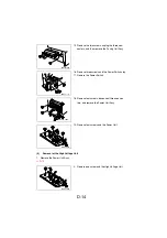
12. Remove one screw and the Paper Take-Up Sole-
noid.
4136D018AA
13. Unhook two tabs and remove the Paper Take-Up
Clutch Gear.
4136D057AA
2. Unhook three tabs and take apart the Paper
Take-Up Clutch Gear then, remove the Torque
Limiter.
4136D043AA
Torque Limiter
Coupling
Gear
4136D044AA
Summary of Contents for D 16G
Page 1: ...DEVELOP SERVICE MANUAL OPTIONS D 16G 4986 7991 00 ...
Page 2: ......
Page 4: ......
Page 10: ......
Page 11: ...GENERAL ...
Page 12: ......
Page 20: ......
Page 21: ...MECHANICAL ELECTRICAL ...
Page 22: ......
Page 54: ......
Page 55: ...MAINTENANCE ...
Page 56: ......
Page 66: ......
Page 67: ...DIS REASSEMBLY ADJUSTMENT ...
Page 68: ......
Page 116: ......
Page 117: ...CONTROL PANEL SERVICE MODE DESCRIPTIONS ...
Page 118: ......
Page 122: ...S 4 2 3 PWB IF Interface Board 4980S004AA USB port IEEE1284 parallel port ...
Page 142: ......
Page 143: ...TROUBLESHOOTING ...
Page 144: ......
Page 184: ...DEVELOP Copyright 2003 Develop Printed in Germany ...
Page 185: ...AF 11 Service Manual ...
Page 188: ...GENERAL ...
Page 190: ...MECHANICAL ELECTRICAL ...
Page 199: ...DIS REASSEMBLY ADJUSTMENT ...
Page 215: ...TROUBLESHOOTING ...
Page 224: ...PF 125 Service Manual ...
Page 226: ...GENERAL ...
Page 228: ...MECHANICAL ELECTRICAL ...
Page 233: ...DIS REASSEMBLY ADJUSTMENT ...


