D-15
3-3.
Removal of Units
(1)
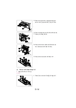
Removal of the IR Unit
1. Remove the Left Cover.
☞
D-7
2. Remove the Right Cover.
☞
D-7
3. Remove the Rear Cover.
☞
D-7
4. Unplug the connector.
4980D007AA
5. Unplug the two flat cables from the Controller/
Mechanical Control Board.
NOTE
•
Be extremely careful not to break the flat cables.
4980D006AA
6. Remove the two screws, unhook the two tabs,
and then remove the IR Unit.
4980D008AB
Summary of Contents for D 16G
Page 1: ...DEVELOP SERVICE MANUAL OPTIONS D 16G 4986 7991 00 ...
Page 2: ......
Page 4: ......
Page 10: ......
Page 11: ...GENERAL ...
Page 12: ......
Page 20: ......
Page 21: ...MECHANICAL ELECTRICAL ...
Page 22: ......
Page 54: ......
Page 55: ...MAINTENANCE ...
Page 56: ......
Page 66: ......
Page 67: ...DIS REASSEMBLY ADJUSTMENT ...
Page 68: ......
Page 116: ......
Page 117: ...CONTROL PANEL SERVICE MODE DESCRIPTIONS ...
Page 118: ......
Page 122: ...S 4 2 3 PWB IF Interface Board 4980S004AA USB port IEEE1284 parallel port ...
Page 142: ......
Page 143: ...TROUBLESHOOTING ...
Page 144: ......
Page 184: ...DEVELOP Copyright 2003 Develop Printed in Germany ...
Page 185: ...AF 11 Service Manual ...
Page 188: ...GENERAL ...
Page 190: ...MECHANICAL ELECTRICAL ...
Page 199: ...DIS REASSEMBLY ADJUSTMENT ...
Page 215: ...TROUBLESHOOTING ...
Page 224: ...PF 125 Service Manual ...
Page 226: ...GENERAL ...
Page 228: ...MECHANICAL ELECTRICAL ...
Page 233: ...DIS REASSEMBLY ADJUSTMENT ...


