M-22
10. PAPER TAKE-UP SECTION
10-1.
Tray 1
(1)
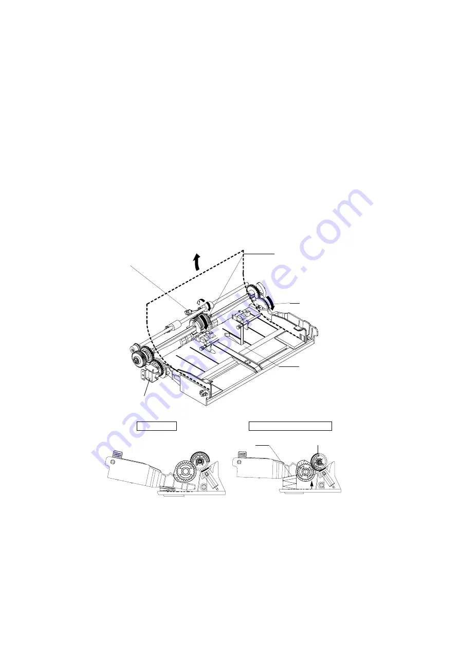
Paper take-up mechanism
• When the Paper Take-Up Solenoid is energized, drive from the Main Motor is transmitted
to the Paper Take-Up Roll through the Paper Take-Up Clutch, turning the Paper Take-Up
Roll.
• At the same time, the Depressing Cam turns so as to raise the Paper Lifting Plate. Then,
the top sheet of paper loaded in the tray is taken up and fed into the printer.
• The actual length of paper is detected based on the period of time through which the
Paper Take-Up Switch remains actuated (or through which the paper moves past the
switch) and the system speed. It is then determined whether or not the actual length
matches the paper length specified on the controller.
Gear with
Depressing
Cam
Tray
Paper Take-Up Solenoid (SL-1)
Paper Take-Up Switch (S1)
Paper Take-Up Roll
4980M006AA
4136M557AA
Tray
Depressing Cam
Standby
When Paper is Taken up
4136M556AA
Summary of Contents for D 16G
Page 1: ...DEVELOP SERVICE MANUAL OPTIONS D 16G 4986 7991 00 ...
Page 2: ......
Page 4: ......
Page 10: ......
Page 11: ...GENERAL ...
Page 12: ......
Page 20: ......
Page 21: ...MECHANICAL ELECTRICAL ...
Page 22: ......
Page 54: ......
Page 55: ...MAINTENANCE ...
Page 56: ......
Page 66: ......
Page 67: ...DIS REASSEMBLY ADJUSTMENT ...
Page 68: ......
Page 116: ......
Page 117: ...CONTROL PANEL SERVICE MODE DESCRIPTIONS ...
Page 118: ......
Page 122: ...S 4 2 3 PWB IF Interface Board 4980S004AA USB port IEEE1284 parallel port ...
Page 142: ......
Page 143: ...TROUBLESHOOTING ...
Page 144: ......
Page 184: ...DEVELOP Copyright 2003 Develop Printed in Germany ...
Page 185: ...AF 11 Service Manual ...
Page 188: ...GENERAL ...
Page 190: ...MECHANICAL ELECTRICAL ...
Page 199: ...DIS REASSEMBLY ADJUSTMENT ...
Page 215: ...TROUBLESHOOTING ...
Page 224: ...PF 125 Service Manual ...
Page 226: ...GENERAL ...
Page 228: ...MECHANICAL ELECTRICAL ...
Page 233: ...DIS REASSEMBLY ADJUSTMENT ...


