S-14
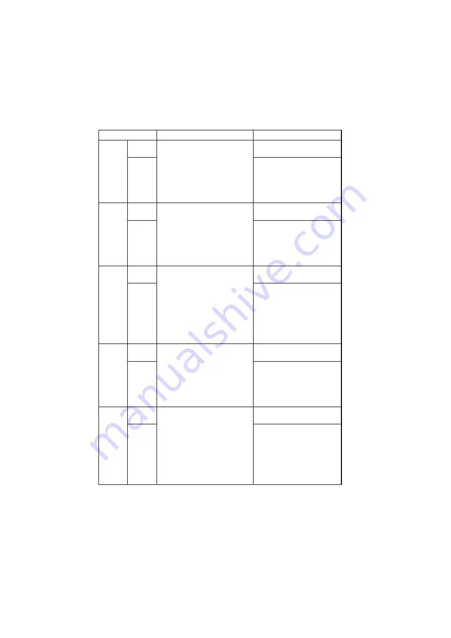
(2)
Adjust
Function
Purpose
Setting Details/Precautions
PRN
MAIN
REGIST
TEST
COPY
To vary and adjust the print start
position in the main scanning
direction.
✽
If the image on the copy devi-
ates in the CD direction
✽
When the PH unit has been
replaced
Press the Start key to begin
printing the test page.
ADJUST
The setting range is 60 to 140.
(1 increment = 0.1 mm)
PRN
SUB
REGIST
TEST
COPY
To vary and adjust the print start
position in the sub-scanning direc-
tion.
✽
If the image on the copy devi-
ates in the FD direction
✽
When the PH unit has been
replaced
Press the Start key to begin
printing the test page.
ADJUST
The setting range is 87 to 113.
(1 increment = 0.46 mm)
CCD
MAIN
ZOOM
TEST
COPY
To adjust for variations in the accu-
racy of IR parts and their mounting
accuracy by varying the scanning
zoom ratio in the main scanning
direction.
✽
When the Timing Belt has been
replaced
✽
When the Scanner Assy. has
been replaced
Press the Start key to begin
printing the test page.
ADJUST
The setting range is 95 to 105.
(1 increment = 0.4%)
CCD
SUB
ZOOM
TEST
COPY
To adjust for variations in the accu-
racy of IR parts and their mounting
accuracy by varying the scanning
zoom ratio in the sub-scanning
direction.
✽
When the Scanner Assy. has
been replaced
Press the Start key to begin
printing the test page.
ADJUST
The setting range is 95 to 105.
(1 increment = 0.4%)
CCD
MAIN
REGIST
TEST
COPY
To adjust for variations in the accu-
racy of IR parts and their mounting
accuracy by varying the scanning
start position in the main scanning
direction.
✽
When the Upper Cover Assy.
(Original Glass) has been
replaced
✽
When the Scanner Assy. has
been replaced
Press the Start key to begin
printing the test page.
ADJUST
The setting range is 90 to 110.
(1 increment = 0.5 mm)
Summary of Contents for D 16G
Page 1: ...DEVELOP SERVICE MANUAL OPTIONS D 16G 4986 7991 00 ...
Page 2: ......
Page 4: ......
Page 10: ......
Page 11: ...GENERAL ...
Page 12: ......
Page 20: ......
Page 21: ...MECHANICAL ELECTRICAL ...
Page 22: ......
Page 54: ......
Page 55: ...MAINTENANCE ...
Page 56: ......
Page 66: ......
Page 67: ...DIS REASSEMBLY ADJUSTMENT ...
Page 68: ......
Page 116: ......
Page 117: ...CONTROL PANEL SERVICE MODE DESCRIPTIONS ...
Page 118: ......
Page 122: ...S 4 2 3 PWB IF Interface Board 4980S004AA USB port IEEE1284 parallel port ...
Page 142: ......
Page 143: ...TROUBLESHOOTING ...
Page 144: ......
Page 184: ...DEVELOP Copyright 2003 Develop Printed in Germany ...
Page 185: ...AF 11 Service Manual ...
Page 188: ...GENERAL ...
Page 190: ...MECHANICAL ELECTRICAL ...
Page 199: ...DIS REASSEMBLY ADJUSTMENT ...
Page 215: ...TROUBLESHOOTING ...
Page 224: ...PF 125 Service Manual ...
Page 226: ...GENERAL ...
Page 228: ...MECHANICAL ELECTRICAL ...
Page 233: ...DIS REASSEMBLY ADJUSTMENT ...


