MOUNTING THE MOTOR
Before installing the motor, be sure it runs in the
right direction. The cutter head must be run clock
wise when viewed from the right side of the machine.
If the motor runs the wrong way, reverse it according
to the manufacturer's directions.
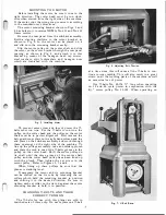
The motor mounting bracket shown in Figs. 2 and
5, has holes in it to receive NEMA No. 224 and No. 225
frame motors.
Remove the rear panel from the sub-base assembly.
Build a slanting platform to the motor bracket, as
shown in Fig. 5, so the motor can be placed on it
and slid onto the mounting bracket easily.
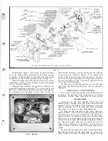
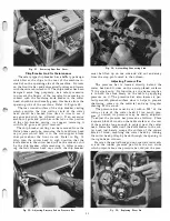
Slip the motor pulley on the motor shaft and slide
the motor on the motor bracket through the rear panel
opening, as shown in Fig. 6, and attach it to this
bracket by means of the hexagon head cap screws,
steel washers, split lockwashers and hexagon nuts
which are furnished with the machine.
Fig.
5.
Installing Motor.
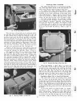
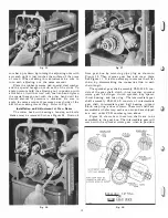
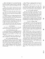
To prevent excess wear and loss of power the V
belts must run true. For the V-belts to run true, the
pulley on the cutter head and the pulley on the motor
shaft must be in perfect alignment. First remove the
belt guard cover plate on the right hand column and the
end plate on the sub-base assembly and work through
these openings on the right side of the machine. To
line up the pulleys accurately, take an ordinary plumb
and place the cord in one of the V -belts grooves in the
pulley on the cutter head. Shift the motor pulley on
its shaft until the same groove of the motor shaft
pulley and the cutter head puliey have been lined up
with the plumb. Then tighten the set screw in the
motor pulley; Refer to Figures 2, 7, and S.
When lining up these pulleys be sure that the
planer is standing level.
If necessary the motor and its mounting bracket
can be shifted on the tie rods by loosening the set
collars which hold the mounting bracket in position
and shifting it in the desired direction. Be sure to
tighten each set collar on the tie rod against the motor
mounting bracket to hold it in position.
CHANGING V-BELTS AND THEIR
CORRECT TENSION
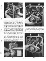
The V -belts for use with this planer are sold in
matched sets of three only. Do not replace one V -belt
Fig.
6.
Adjusting Belt Tension.
at a time since this will cause all the V -belts to con
tinue to wear rapidly. This will also result in a great
strain on all the working parts of the machine as well
as excessive loss of power.
Use V-belts No. 49-176 71" long when operating
on 25 and 50 cycle power in conjunction with the
SYz" motor pulley No. 22-105. When operating on
Fig.
7.
V-Belt Drive.
Summary of Contents for Milwaukee PM-1738
Page 1: ...13x5 INCH DELTA MILWAUKEE 7 7 1M rJ6fiUAKJ PM 1738 ...
Page 2: ......
Page 27: ......
Page 28: ......


