ASSEMBLY
Remove the crate. Wipe the protective coating
thoroughly from the working parts of the machine.
Unpack the other items in the separate cartons which
come with the planer, and wipe the protective coating
from these parts.
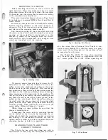
Place the hand-wheel assembly on the machine by
slipping its hub over the hand-wheel shaft of the
raising mechanism which projects from the left side
of the base casting. Tighten the set screw in the hub
of the hand-wheel assembly against the flat of the
shaft by using the 3/16" hexagon wrench SP-3.
To assemble the sub-base proceed as follows: Set
two legs on end and fasten a tie angle to them by
using the %-16 x Va" hexagon head cap screws and
the %" split lockwashers. Attach the two tie angles
to the four legs as described above. Slip the motor
bracket assembly on the rear tie rod, then place a
set collar on each side. Fasten the tie rod to the tie
angle using the Yz-13 x
I"
hexagon head cap screws
and the Yz" split lockwashers. Place the two eye bolts
on the remaining front tie rod and thread a %-24
hexagon nut on each of them. Install the tie bar so its
two outer holes fall over the ends of the eye bolts let
ting it rest on the hexagon nuts. Place a %" split
lockwasher and a :Y;!"-24 hexagon nut on the end of
each eye bolt loosely.
Swing the motor bracket assembly down on the
front tie bar and match its holes with the two inner
holes of the tie bar. Insert a %-24 x 1" hexagon head
cap screw through each of the two holes in the tie
bar from the bottom, placing a %" split lockwasher
and a �/g"-24 hexagon nut on top, then secure the motor
bracket assembly in position by tightening these nuts.
In some cases the tie bar may be mounted on top of
the motor bracket assembly if necessary.
Fasten the side, front and rear panels to the cast
iron legs by means of the soecial 5
/
16-18 x Yz" truss
head machine screws provided with the sub-base as
sembly. Refer to Fig. 2.
The base of the machine has four tapped holes in
it which are used to mount it directly on the sub-base
assembly using the %-11 x 2" hexagon head cap
screw with a %" split lockwasher from beneath the
top of each leg and screwing the end of each cap screw
into the tapped hole of the base. The additional two
11/16" diameter holes in each tie angle of the sub-base
assembly are provided for mounting the machine to
a skid or permanently mounting it to the shop floor.
However, it is not necessary to bolt the machine down
as the base or sub-base is built to stand on any level
surface.
ST ARTERS AND ELECTRICAL CONNECTIONS
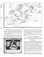
The magnetic starters available with start and stop
reset push buttons are conveniently mounted in the
left-hand column as shown in Fig. 4 so they become
an integral part of the machine. Mounting the starters
in this manner provides for a permanent safe connec
tion and permits the machine to be easily wired from
any convenient power outlet. All starters available for
this machine are open type (without box enclosure) ,
operate on AC current and are for either single or 3
phase motors only.
No. 49-386 Magnetic starter available for 220 volt
operation, open type (without box enclosure) with
heater coils.
No. 49-387 Magnetic starter available for 440 volt
operation, open type (without box enclosure) with
heater coils.
4
The following heater coils are available for the
above electrical starters :
PLR-151 Pair of heater coils for use with No. 49-386
magnetic starter. This pair of heater coils is used in
conjunction with a 3 hp, 3 phase, 230 volt motor and
have a rating of 7.2 amperes.
PLR-152 Pair of heater coils for use with No. 49-387
magnetic starter. This pair of coils is used in con
junction with a 3 hp, 3 phase, 440 volt motor and have
a rating of 3.5 amperes.
PLR-153 Pair of heater coils for use with No. 49-386
magnetic starter. This pair of coils is used in con
junction with a 3 hp, 1 phase, 230 volt motor and have
a rating of 17 amperes.
Please specify the motor horsepower, phase, volt
age, amperage and frequency when ordering the above
magnetic starters.
Use No. 49-389 three No. 12 gauge wire two feet
long armored cable when connecting the switch and the
motor. All three wires of the armored cable are used
when installing a three phase motor. Only two wires
of the armored cable are used when installing a single
phase motor and the remaining wire is easily removed.
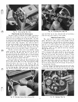
Fig.
4.
Electrical Starter Mounted in Left-Hand Column Casting.
CONNECTING TO POWER LINE
When connecting the power line to the starter box
have a licensed electrician check the following :
1. The line voltage, phase and frequency match the
the motor name plate.
2. The overload heater coils used in the starter box
must be the right size for the full load amperage
rating of the motor.
3. The proper size of wire is used in connecting
the machine to the power line to obtain proper
voltage. Using too small a wire will cause an
excessive loss of power.
4. The fuse used has enough capacity to carry the
starting and full load current of the motor.
5. The magnetic starter is of the proper voltage so
its magnetic coil matches the line voltage.
6. Make sure the motor rotates in the proper di
rection.
Summary of Contents for Milwaukee PM-1738
Page 1: ...13x5 INCH DELTA MILWAUKEE 7 7 1M rJ6fiUAKJ PM 1738 ...
Page 2: ......
Page 27: ......
Page 28: ......


