I'ig.
I�.
Setting Finished Size Scale.
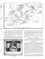
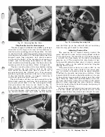
The pressure on these rolls can be adjusted easily
by loosening the special hexagon lock nuts on the top
of each column and turning the hexagon socket ad
justing screws until the desired pressure is obtained.
Be sure to adjust the screws on each side of the rolls
the same amount to maintain even pressure across
the entire length of each roll. Tighten the special hexa
gon lock nuts after making the adjustment. Each feed
roll has two adjusting screws which hold it in posi
tion, the front two screws are for the in-feed roll and
the rear two screws are for the out-feed roll.
Caution: If the pressure on each side of each feed
roll is not even the stock may not feed straight as it
is being fed through the machine. Refer to Fig. 19.
The serrated in-feed roll is protected from chips
by the baffle type design of the chip breaker. This
feed roll will pick up a certain amount of chips and
dust after a considerable amount of use, resulting in
the serrations becoming filled or loaded. The smooth
out-feed roll will collect gum and pitch after consider
able use, resulting in picking up chips and packing.
Caution : Never scrape these feed rolls with a sharp
instrument since gum and pitch will be picked up that
much faster. When these conditions exist, we suggest
the operator remove the gum and pitch which has been
mixed in with chips and dust with Delta gum and
pitch remover to maintain smooth positive feed.
Fig.
19.
Adjusting Pressure, on Feed Rolls.
10
Replacing Chain Assemblies
The chain assemblies are of a continuous anti-fric
tion roller type which connect solid steel sprockets. If
either chain should break we suggest replacing
'
it.
To replace these chains proceed as follows:
_
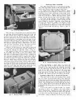
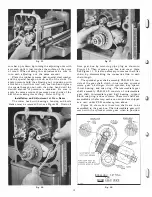
Drain
the gear box of oil, see Figure 20. Remove the shifter
assembly of the clutch mechanism as described under
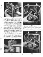
"Clutch Mechanism." Remove the four special slotted
head nuts, and the six fillister head cap screws which
secure the gear box casting to the left-hand column.
The fiber gasket between the machined surfaces
of the gear box and left-hand column casting will be
quite difficult to separate; therefore, when removing
the gear box casting we suggest the operator strike
it moderately with a mallet. Do not strike the fine
grey iron gear box casting with a steel faced hammer
since this may break the casting. Refer to Figs. 2 1
and 23.
Fig.
20.
Removing Pipe Plug to Drain Gear Box.
When assembling a chain place it around the
steel sprockets of the in and out-feed rolls and then
connect its two ends together by installing the body
of the connecting link through the two holes in the
ends of the chain. Slip the plate of the connecting
link over the projecting ends of the connecting link
body and secure it in place by the spring clip. To dis
assemble the chains reverse the above procedure.
Replacing Shear Pin In Feed Roll Sprocket
The solid steel in-feed roll sprocket has a shear
pin in it which can be replaced easily. The reason for
connecting the solid steel sprocket to the in-feed roll by
means of a shear pin is for overload protection; for in
stance, if the load becomes too great because too heavy
a cut is being taken on the stock, the shear pin will
break before breaking the anti-friction roller type chain
assembly.
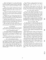
If the brass shear pin should break, we suggest
removing it with a Ys" diameter steel rod using a
small steel hammer. Replace the brass shear pin as
shown in Fig. 24. Be sure that the hole in the sprocket
is in line with the hole through the end of -the feed
roll before trying to hammer the shear pin in place.
Summary of Contents for Milwaukee PM-1738
Page 1: ...13x5 INCH DELTA MILWAUKEE 7 7 1M rJ6fiUAKJ PM 1738 ...
Page 2: ......
Page 27: ......
Page 28: ......


