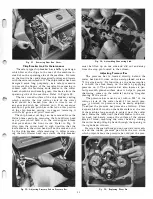
Fig.
33.
Next check the up and down movement of inter
mediate gear as shown in backlash setting Figure 28.
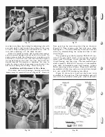
When the proper location has been established, tighten
the three set screws in lock plate PLR-94 as shown
in Figures 29 and 30. Also tighten the single cap screw
that holds lock plate PLR-394 and sprocket gear shaft
in place.
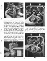
To determine the amount of backlash in the sprock
et gear shaft, hold the oil slinger as shown in Figure 31.
and move it back and forth, there should be 4 to 6
thousandths of an inch backlash movement.
The intermediate gear, intermediate gear shaft.
and shaft support are in line as assembled and must
be located in the center of the worm on the sprocket
worm gear. The backlash on the intermediate gear
Fig.
34.
Removing Shifter Assembly.
14
should be 8 to 10 thousandths of an inch. This is deter
mined by moving bronze gear back and forth, as shown
in Figure 32.
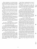
After the gears have been adjusted and set, it will
be necessary to check the clearance between the oil
slinger and the bronze gear, this clearance should not
exceed .010 of an inch. A .010" feeler is used for
measuring this clearance, as shown in Figure 33. Should
this clearance be more than .010" the oil slinger disc
will have to be bent towards the gear on the inter
mediate shaft. This can be don� by rapping or bending
the disc until the correct clearance has been obtained.
A clearance of .010" or less must be held to insure the
proper lubrication of the gears. Use a good grade of
SAE, 140 steam cylinder oil only. It is available in one
gallon containers at the factory. See parts list.
11-2-50
BAR
BLADE
DI STANCE THROAT B A R MUST
BE M AINTAINED F ROM EDGE
OF KNI FE BLADE TO INSURE
COR RECT CUTTING ACTION
Fig.
35.
Clutch Mechanism
The clutch mechanism is provided on this machine
to enable the operator to instantly stop and start the
feed without shutting off the motor. The shifter as
sembly is easily moved to start (engage) or stop (dis
engage) the feed by finger tip control. To remove the
shifter assembly from the gear box, drain the oil
from the gear box as indicated in Figure 20. Remove
the four machine screws, which hold the cover plate
and paper gasket in place on the gear box. Loosen the
hexagon socket set screw in shifter fork PLR-350
and also set screw in gear box casting, as indicated in
Figure 34, using 5/32" hexagon wrench SP-2. The
shifter assembly can then be removed from the casting.
The two steel coil springs and indexing pins which
are incorporated within the indexing collars on the
Summary of Contents for Milwaukee PM-1738
Page 1: ...13x5 INCH DELTA MILWAUKEE 7 7 1M rJ6fiUAKJ PM 1738 ...
Page 2: ......
Page 27: ......
Page 28: ......


