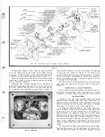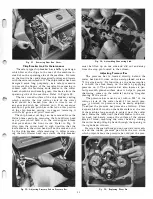
shifter assembly can be removed easily by loosening
the hexagon socket set screw in the outer indexing
collar using the 5/32" hexagon wrench SP-2, remov
ing the shifter handle from the shifter rod and slipping
the small indexing collar forward enough to remove
the steel pins and coil springs. Be sure when assem
bling this mechanism that the outer indexing collar
is tight against the large indexing collar before locking
it in position by tightening its hexagon socket set
screw. If this is not done properly slippage will occur
and the shifter assembly will not be held properly in
the feed position. Refer to Fig. 11.
When the shifter assembly is parallel to the column
casting the machine is in the idling position. Move
the shifter handle to the right to engage the machine
in the feed position.
Resetting Knife Blades In Cutter Head
The knife blades in the cutter head are set at the
factory to a true cutting circle of 2 9
/
16". If the knife
blades are removed or adjusted in any way, care must
be exercised in resetting them.
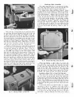
To reset the knife blades in the cutter head proceed
as follows: Turn the nine special hexagon head set
screws of the steel throat bar in the full amount using
the double end 5/16" open wrench J-40 provided
with the machine, and place this bar into the groove
of the cutter head. Screw one special collar adjusting
screw in the cutter head body giving it a few turns.
Slide a knife blade into the cutter head until its slotted
edge engages the collar of the adjusting screw. Engage
the slot on the opposite edge of the knife blade with
another special collar adjusting screw and
'
screw it
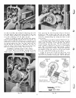
in the cutting head a few turns. Refer to Fig. 13.
Turn each of the nine special hexagon head adjust
ing screws in the throat bar out a few turns. Repeat
this operation as many times as necessary until the
throat bar is held lightly against the knife blade. Do
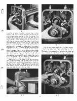
Fig.
36.
Checking Height of Knife Blade.
15
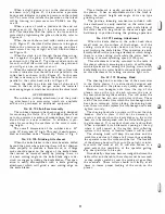
Fig.
37.
Adjusting Height of Knife Blade.
not turn each adjusting screw out the full amount
taking one at a time, because all nine screws must be
turned out gradually to insure the same amount of
pressure across the entire length of the knife blade.
To adjust the knife blade to the true cutting circle,
place the knife gauge provided with this machine over
the knife blade in the cutter head then turn the special
collar adjusting screws at each end of the kriife blade
until the knife blade just touches the center of the
knife gauge across its entire length. Tighten the knife
blade securely in place by turning each of the nine
special hexag�n head adjusting screws gradually out
in the throat bar as described above.
Each knife blade in the cutter head must be ad
justed as described above to maintain a true cutting
circle. Refer to Figs. 35, 36 and 37.
Important: An allowance of .008" for grinding
stock per blade has been provided in the knife gauge
which is furnished with this machine.
CARE AND SHARPENING OF
CUTTER HEAD KNIFE BLADES
The three high-speed steel knife blades in the cutter
head should plane the stock clean, and smooth without
exerting an unreasonable amount of force. After a
considerable amount of use, the knife blades in the
cutter head will become dull and will no longer cut
smoothly, but will tend to gouge the stock and leave
the surface rough. Continued operation of dull knife
blades will result in a great strain on the machine, the
cutter head assembly, and will cause decreased pro
duction.
If nicks should appear on the surface of the edge
of the knife blades, they should be eliminated, since
evidence will appear on the surface of the material
being planed. These nicks are easily removed by joint
ing or grinding or both depending upon the size of the
nick and condition of the knife blades.
Summary of Contents for Milwaukee PM-1738
Page 1: ...13x5 INCH DELTA MILWAUKEE 7 7 1M rJ6fiUAKJ PM 1738 ...
Page 2: ......
Page 27: ......
Page 28: ......

