(2) PLR-116 HEX NUT--{>
SPLIT LOCKWASHER SP-1705
(2) PLR-84
CAP (4) PLR-61
SP-231 SET
8REAKER STUD PLR-131
ADJUSTING SCREW (4) PLR-62
PLR-86-R CUTTER HEAD
(2)
(4) PLR-97
SP-777 CAP SCREW
i
(2)PLR-82 RUBBER PRESSURE
HAND SUPPORT RING PLR-112
,�-M(A)CH
�
CREW
(2) PLR-81 ADJUSTING
CHIP BREAKER PLR-6
6 PL -73
(4) SP-707 MACH
CBS-125
COVER PLATE
�
DRIVE SCREW (2) SP-2250
PLR-66
PLR-7 PESSURE BAR
''''.J
\
ACH SCREW (4) SP-707
_
:
CAP SCR
(2)
SP-3303
_.
_
PLR-III LEFT HAND SUPPORT
/
MACH
/
/
PLR-73
/
PLR-69 REAR TIE ROD
'\
I
�
,
'
�/'--
I
I
�
(2) SP-670 CAP
-
\
(2)
SP-1231 HEX
./
M
��?�l
DB
CfJ
E
�
F
./
I
(3) PLR-60
SPLIT
\
TH
�
OAT BAR
LOCKWASHER,
/
RIGHT HAND
.>'.
I
(271J
�
32
f
L
:
Ei
9SCR'"
(2) SP-1705
COLUMN
<.J
FRONT S
�!
ll
:�:
-
�����
O
PL
�
TE p
�
�
:
�
3 MATC
�
i
�:
�
�
!
5
�
F 3
STOP BUTTON (2) PLR-56
BLOCK ASSEMBLY (2) PLR -15-5
ADJ
/"'>
(6)
FIBER WASHER
LTA-462
SCREW (4) PLR-13
SP-2 HEX W RENCH
J-40 OPEN END W RENCH
CUTTER HEAD
BEARING PLR-136
_
PLR-68-S
_
�M��t�
(
�f�A
�
4
62
IN FEED
ROLL
PLR
48
RETAINING SCREW (4) PLR-13
HI-PRO-KE Y SP-2603
�
FIBER WASHER (4) HDP-122
SP-4 HEX W RENCH
PLR-150 KNIFE GAUGE
DUST SLINGER PLR-124
BEARING PLR-136
HOUSING PLR-16
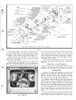
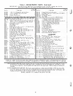
CUTTER HEAD, IN AND OUT- FEED ROLLS, CHIPBREAKER, PRESSURE
BAR AND RIGHT-HAND COLUMN ASSEMBLY
5-23-51
Fig.
13.
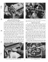
or lowering the adjusting nut by means of a small steel
rod
y,I"
in diameter and approximately 6" long. After
making the adjustment tighten the fillister head ma
chine screw in the adjusting nut support and take an
other trial cut as described above. Re-check the pieces
of wood by means of an accurate scale. If a slight cor
rection is needed, readjust the table until the setting is
correct. Refer to Fig. 14.
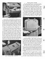
Adjusting Table Gibs
The table casting has machined surfaces which
ride in relation to a machine surface of each column.
Between each side of the table casting and the columns
we have incorporated a steel gib to take up all play
between these machined surfaces. This adjustment has
been carefully made at the factory, but we suggest
checking the table to see if any play does exist.
If the table cannot be raised or iowered easily,
or if the table is too loosely set, an adjustment is
needed. To make this adjustment proceed as follows :
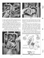
Loosen the hexagon jam nut which locks the cone
pointed adjusting screw and loosen or tighten each
adjusting screw approximately
Yz
turn. Lock each
screw after readjusting it by tightening its hexagon
jam nut. Be sure to loosen or tighten each screw the
same amount to obtain a good tight sliding fit between
the table and column castings. We suggest the op
erator adjust the uppermost screw first, then the bot
tom screw and finally the center screw. Refer to Fig. 15.
Adjusting Table Rollers and Thei r Maintenance
The table rollers (idlers) play an important part to
keep the stock feeding smoothly. These rollers prevent
the stock from dragging on the table surface while
the cutting head is planing the stock. The table rollers
have been accurately set at the factory .005" above
the table surface which is sufficient for most types
of wood.
Do not readjust these rollers unless it is absolutely
necessary. If the material drags to such an extent on
8
the table surface while it is being planed so that it
prevents the stock from being fed smoothly an ad
justment should be made. When making this adjust
ment proceed as follows: To accurately set these
rollers above the table surface it should be done by
means of a dial indicator. Run the dial indicator across
the entire surface of each roll to get them absolutely
parallel in relation to the table surface. If the dial
indicator shows that these rolls are not parallel a
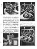
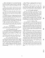
correction should be made. Refer to Figs. 3 and 16.
Loosen the hexagon jam nut which locks each
hexagon head shoulder bolt located beneath each side
of the table casting and adjust each bolt the amount
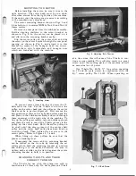
Fig.
14.
Leveling Table.
Summary of Contents for Milwaukee PM-1738
Page 1: ...13x5 INCH DELTA MILWAUKEE 7 7 1M rJ6fiUAKJ PM 1738 ...
Page 2: ......
Page 27: ......
Page 28: ......


