background image


c.


If the connector has a release tab, press the release tab as you grasp the card by its top corners, and ease it out of its connector.  


6.

If you are removing the card permanently, install a filler bracket in the empty card-slot opening.  


7.

Before you rotate the card retainer back into place, ensure that:  
 

l


The tops of all cards and filler brackets are flush with the alignment bar. 


l


The notch in the top of each card or filler bracket fits around the alignment guide. 


8.

Connect any cables that should be attached to the card.  
 

See the documentation for the card for information about the card's cable connections. 


9.

Rotate the card retainer back into its original position; push its tip so that its tab clicks into place.  


NOTE: 

Installing filler brackets over empty card-slot openings is necessary to maintain FCC certification of the computer. The brackets also keep dust 

and dirt out of your computer.


NOTE: 

For extra security, remove the alignment guide (an upside-down screw) and screw it in right side up to secure a card.

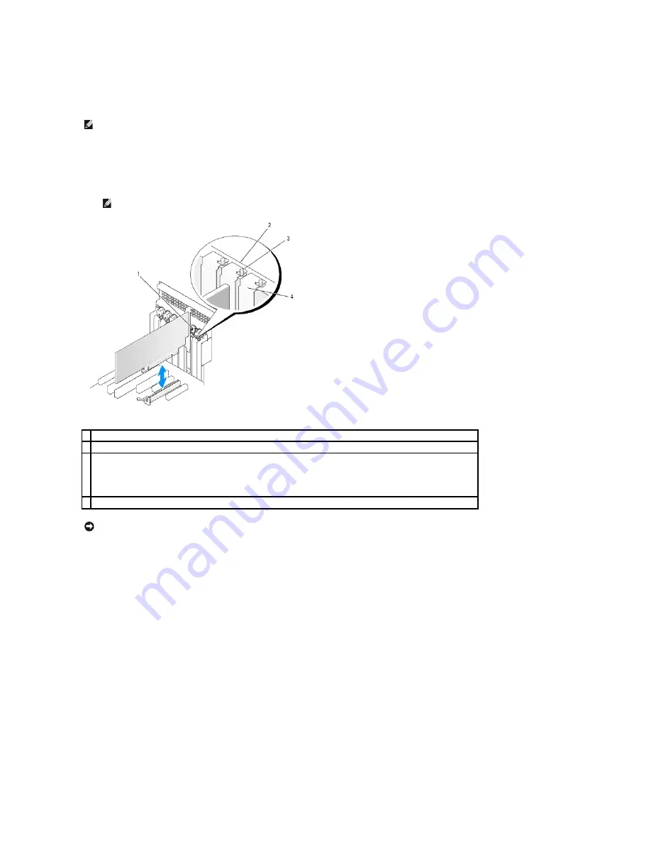
1  card retainer 

2  alignment bar 

alignment guide 


NOTE: 

For extra security, remove the alignment guide (an upside-down screw) and screw it in right side up to secure a card. 

4  filler bracket 


NOTICE: 

Do not route card cables behind the cards. Cables routed behind the cards could cause damage to the equipment.

Summary of Contents for Precision Workstation 690

Page 1: ...ther trademarks and trade names may be used in this document to refer to either the entities claiming the marks and names or their products Dell Inc disclaims any proprietary interest in trademarks and trade names other than its own Model DCDO August 2006 P N MD488 Rev A02 Information About Your Computer About Your Computer Advanced Features Copying CDs and DVDs Before You Begin Computer Stand Rem...

Page 2: ...rchangeable 4 5 25 inch drive bay with special 3 5 inch drive panel plate Can hold a CD DVD drive or a Media Card Reader a floppy drive or a SATA hard drive in a 5 25 inch drive bay carrier The drive panel plate shown here is only for use with a floppy drive or Media Card Reader it can be installed in front of any of the four 5 25 inch drive bays For more information see Drive Panels NOTE Hard dri...

Page 3: ... the microphone connector to attach a personal computer microphone for voice or musical input into a sound or telephony program 11 headphone connector Use the headphone connector to attach headphones 12 network link light The network link light is on when a good connection exists between a 10 Mbps 100 Mbps or 1000 Mbps or 1 Gbps network and the computer 13 diagnostic lights 4 Use these lights to h...

Page 4: ...nd of a network cable to either a network jack or your network or broadband device Connect the other end of the network cable to the network adapter connector on your computer A click indicates that the network cable has been securely attached NOTE Do not plug a telephone cable into the network connector On computers with an additional network connector card use the connectors on the card and on t...

Page 5: ...can be modified through system setup see System Setup 1 power supply 2 hard drive bay 3 memory shroud NOTICE The memory shroud holds the optional memory riser cards in place its thumbscrews must be sufficiently tight in order to secure the risers and to avoid damage 4 front fan 5 card fan 6 5 25 inch drive bay with 3 5 inch drive panel plate 7 5 25 inch drive bay ...

Page 6: ...wired as x4 SLOT7_PCIE 8 auxiliary hard drive LED connector AUX_LED 25 PCI X card slot SLOT6_PCIX 9 air temperature sensor connector 26 PCI X card slot SLOT5_PCIX 10 battery socket BATTERY 27 PCI card slot SLOT4_PCI NOTE This slot is not available in the dual graphics configuration 11 SATA connectors SATA_0 SATA_1 SATA_2 28 PCI Express x8 card slot wired as x4 SLOT3_PCIE NOTE In the dual graphics ...

Page 7: ...nector FAN_MEM 15 hard drive connector HDD_2 32 white memory module connectors DIMM_1 4 support memory modules or memory module risers 16 hard drive connector HDD_1 33 black memory module connectors DIMM_5 8 support memory modules only when no memory riser cards are installed otherwise these must be left empty 17 hard drive connector HDD_0 34 primary processor connector CPU_0 Device Color Hard dri...

Page 8: ...ed with industry standard management software It supports instrumentation that conforms to SNMP DMI and CIM industry standards Dell OpenManage Client instrumentation which is based on DMI and CIM is available for your computer For information on IT Assistant see the Dell OpenManage IT Assistant User s Guide available on the Dell Support website at support dell com LegacySelect Technology Control M...

Page 9: ...nter to access the menu 4 Use the down arrow key to select Chassis Intrusion 5 Use the left and right arrow keys to select an option setting 6 Exit system setup Option Settings l On If the computer cover is opened the setting changes to Detected and the following alert message displays during the boot routine at the next computer start up Alert Cover was previously removed l On Silent default If t...

Page 10: ...mplete step 5 1 Enter system setup and verify whether an Unlock Setup field is present under Security see System Setup 2 If the Unlock Setup field is present a Use the arrow keys to navigate to the Unlock Setup field b Press Enter to access the field c Type in the administrator password and press Enter 3 Use the arrow keys to navigate to the System Password field and then press Enter 4 Type your n...

Page 11: ...of unsuccessful password attempts 3 System halted Must power down Even after your computer is turned off and on the previous message is displayed each time you type an incorrect or incomplete system password Deleting or Changing an Existing System Password To escape from the field without assigning a system password press Esc at any time before you complete step 5 1 Enter system setup and verify w...

Page 12: ...se sensitive Certain key combinations are not valid If you enter one of these combinations the speaker emits a beep As you press each character key or the spacebar for a blank space a placeholder appears in the field 5 Press Enter If the new administrator password is less than 15 characters the whole field fills with placeholders 6 To confirm your password type it a second time in the Confirm New ...

Page 13: ...ead the current amount of memory or set the type of hard drive installed Before you use system setup it is recommended that you write down the system setup screen information for future reference Entering System Setup 1 Turn on or restart your computer 2 When the blue DELL logo is displayed you must watch for the F2 prompt to appear 3 Once this F2 prompt appears press F2 immediately 4 If you wait ...

Page 14: ... the USB device and move it so it becomes the first device in the list Drives SAS Controller On default Enables or disables the internal SAS controller Diskette Drive Internal default Enables and disables the floppy drives and sets read permission for the internal floppy drive Off disables all floppy drives USB disables the internal diskette drive and enables a USB floppy drive if the USB controll...

Page 15: ...default setting automatically configures a connector to a particular designation COM1 or COM3 Serial Port 2 Auto default Determines how the serial port operates Auto the default setting automatically configures a connector to a particular designation COM2 or COM4 PS 2 Mouse Port On default Enables or disables the integrated legacy PS 2 compatible mouse controller Video Primary Video PEG default Th...

Page 16: ...t commands the system to return to the last power state the system was in just before it was turned off Auto Power On Off default Sets the computer to automatically turn on Off disables this feature Everyday turns the computer on every day at the time set in Auto Power Time Weekdays turns the computer on every day from Monday through Friday at the time set in Auto Power Time NOTE This feature does...

Page 17: ... used for the current boot only Defaults Event Log Allows you to view the Event Log Entries are marked R for Read and U for Unread Mark All Entries Read puts an R to the left of all the entries Clear Log clears the Event Log POST Behavior Fastboot On default When enabled this feature reduces computer startup time by bypassing some compatibility steps Off does not skip any steps during computer sta...

Page 18: ...e Boot Device for the Current Boot Clearing Forgotten Passwords 1 Follow the procedures in Before You Begin NOTE To boot to a USB device the device must be bootable To make sure your device is bootable check the device documentation NOTE Write down your current boot sequence in case you want to restore it NOTE To boot to a USB device the device must be bootable To ensure that your device is bootab...

Page 19: ...tup password See System Setup Clearing CMOS Settings 1 Follow the procedures in Before You Begin 2 Remove the computer cover see Removing the Computer Cover 3 Reset the current CMOS settings a Locate the password and CMOS jumpers RTCRST on the system board see System Board Components b Remove the password jumper plug from its pins c Place the password jumper plug on the RTCRST pins and wait approx...

Page 20: ...ide a single CPU package thereby increasing computing efficiency and multi tasking ability It is recommended that you use the Microsoft Windows XP Service Pack 1 SP1 or higher operating system because Windows XP is optimized to take advantage of Hyper Threading technology While many programs can benefit from Hyper Threading and dual core technology some programs may have not been optimized for the...

Page 21: ...es to create a large virtual drive Data striping allows one of the drives to read data while the other drive is searching for and reading the next block Another advantage of a RAID level 0 configuration is that it utilizes the full capacities of the drives If you have two 120 GB drives installed you have 240 GB on which to store data RAID Level 1 RAID level 1 uses a data redundancy storage techniq...

Page 22: ...a A minimum of three drives is required to create a RAID level 5 configuration RAID Level 10 RAID level 10 uses a combination of striping and mirroring methods It requires four drives The drives are broken up into mirroring pairs and then the data that is written to the RAID configuration is striped across all four drives Data can be accessed quickly due to the striping of data however each piece ...

Page 23: ...striping Additional information is available on the configuration screen Creating a RAID Level 0 Configuration Follow these steps to create a RAID 0 volume on a SAS 5 iR controller that does not currently have a RAID volume configured 1 Select a controller from the Adapter List in the Configuration Utility 2 Select the RAID Properties option 3 Select Create IS Volume when you are prompted to creat...

Page 24: ...drives cannot be used in the same RAID volume l Drives must have 512 byte blocks and must not have removable media l There can only be 2 hard drives per RAID volume l Press C and then select Save changes when the RAID volume has been fully configured l Exit this menu to save the changes The Configuration Utility will pause while the RAID volume is being created Creating a Second RAID Volume The SA...

Page 25: ...pacity or larger capacity 2 Check your management application or the RAID Configuration Utility Ctrl C to ensure synchronization started automatically 3 Enter the RAID Configuration Utility Ctrl C 4 From the Adapter List screen select the controller that contains the degraded RAID volume 5 From the Adapter Properties screen select RAID Properties 6 Press Alt N until the degraded RAID level 1 volum...

Page 26: ...connector CAUTION Before you begin any of the procedures in this section follow the safety instructions in the Product Information Guide CAUTION To guard against electrical shock always unplug your computer from the electrical outlet before opening the cover CAUTION A new battery can explode if it is incorrectly installed Replace the battery only with the same or equivalent type recommended by the...

Page 27: ...ectrical outlets and turn them on 10 Enter system setup see Entering System Setup and restore the settings that you recorded when you removed the existing battery Back to Contents Page 1 system battery 2 battery socket tab 3 positive side of battery connector 4 battery socket CAUTION Your computer is heavy it has an approximate minimum weight of 55 lbs and can be difficult to maneuver Seek assista...

Page 28: ... CAUTION The computer stand should be installed at all times to ensure maximum system stability Failure to install the stand could result in the computer tipping over potentially resulting in bodily injury or damage to the computer NOTICE To avoid losing data save and close all open files and exit all open programs before you turn off your computer CAUTION Your computer is heavy it has an approxim...

Page 29: ...tempting to lift move or tilt it this computer requires a two man lift Always lift correctly to avoid injury avoid bending over while lifting See your Product Information Guide for other important safety information CAUTION The computer stand should be installed at all times to ensure maximum system stability Failure to install the stand could result in the computer tipping over potentially result...

Page 30: ...therwise customizing it for your computer If you are replacing a card uninstall the existing driver for the card Installing an Expansion Card 1 Follow the procedures in Before You Begin 2 Remove the computer cover see Removing the Computer Cover CAUTION Before you begin any of the procedures in this section follow the safety instructions in the Product Information Guide CAUTION To guard against el...

Page 31: ... the card by its top corners and ease it out of its connector 7 Prepare the card for installation See the documentation that came with the card for information on configuring the card making internal connections or otherwise customizing it for your computer 8 If the card is full length align it between the plastic card guides on the card fan 9 Position the card so that it is aligned with the slot ...

Page 32: ...ignment guide 12 Rotate the card retainer until it snaps into place 1 bracket within slot 2 bracket caught outside of slot 3 card fully seated 4 card not fully seated NOTE For extra security remove the alignment guide an upside down screw and screw it in right side up to secure a card 1 card retainer 2 alignment bar 3 alignment guide NOTE For extra security remove the alignment guide an upside dow...

Page 33: ...g to Off b Connect external audio devices to the sound card s connectors Do not connect external audio devices to the microphone speaker headphone or line in connectors on the back panel 18 If you installed a network adapter card and want to disable the integrated network adapter a Enter system setup select Integrated NIC and then change the setting to Off b Connect the network cable to the networ...

Page 34: ... computer is heavy it has an approximate minimum weight of 55 lbs and can be difficult to maneuver Seek assistance before attempting to lift move or tilt it this computer requires a two man lift Always lift correctly to avoid injury avoid bending over while lifting See your Product Information Guide for other important safety information CAUTION The computer stand should be installed at all times ...

Page 35: ...or information about the card s cable connections 9 Rotate the card retainer back into its original position push its tip so that its tab clicks into place NOTE Installing filler brackets over empty card slot openings is necessary to maintain FCC certification of the computer The brackets also keep dust and dirt out of your computer NOTE For extra security remove the alignment guide an upside down...

Page 36: ... driver for the removed card See the documentation that came with the card 16 If you removed a sound card a Enter system setup select Integrated Audio and then change the setting to On b Connect external audio devices to the audio connectors on the back panel of the computer 17 If you removed a network adapter card a Enter system setup select Integrated NIC and then change the setting to On b Conn...

Page 37: ...o or downgrade from a dual graphics configuration you will need additional parts that can be ordered from Dell See Contacting Dell CAUTION Your computer is heavy it has an approximate minimum weight of 55 lbs and can be difficult to maneuver Seek assistance before attempting to lift move or tilt it this computer requires a two man lift Always lift correctly to avoid injury avoid bending over while...

Page 38: ... a filler bracket in the empty card slot opening 9 Before you rotate the card retainer back into place ensure that l The tops of all cards and filler brackets are flush with the alignment bar l The notch in the top of each card or filler bracket fits around the alignment guide 1 release tab 2 card retainer 1 PCI Express x16 card 2 securing tab 3 PCI Express x16 card slot NOTE Installing filler bra...

Page 39: ...n push its tip so that its tab clicks into place 12 Press the card retention device back into its original position push it down until it clicks into place 1 bracket inside of slot 2 bracket caught outside of slot 3 fully seated card 4 not fully seated card NOTICE Do not route card cables behind the cards Cables routed behind the cards could cause damage to the equipment 1 release tab 2 card retai...

Page 40: ...locate the PCI Express x1 card slot To remove a PCI Express card see Removing an Expansion Card 1 Follow the procedures in Before You Begin 2 Remove the computer cover see Removing the Computer Cover 1 card retention device 2 tab NOTICE To connect a network cable first plug the cable into the network port or device and then plug the cable into the computer NOTE To upgrade to or downgrade from a du...

Page 41: ...from a Dual Configuration 6 Prepare the card for installation See the documentation that came with the card for information on configuring the card making internal connections or otherwise customizing it for your computer 7 If the card is full length align it between the plastic card guides on the card fan 8 Position the card so that it is aligned with the slot and the securing tab if present is a...

Page 42: ...d retainer back into its original position push its tip so that its tab clicks into place 13 Press the card retention device back into its original position push it down until it clicks into place 2 securing tab 3 PCI Express x16 card slot NOTICE Ensure that you release the securing tab to seat the card If the card is not installed correctly you may damage the system board NOTE For extra security ...

Page 43: ...sult in degraded graphics performance 1 graphics card bridge not present on some dual graphics configurations 2 power connectors 2 3 dual PCI Express graphics cards NOTICE To connect a network cable first plug the cable into the network port or device and then plug the cable into the computer NOTE To upgrade to or downgrade from a dual graphics configuration with the graphics riser card you will n...

Page 44: ... Riser Card Follow the steps for graphics riser card removal in reverse order Back to Contents Page CAUTION The computer stand should be installed at all times to ensure maximum system stability Failure to install the stand could result in the computer tipping over potentially resulting in bodily injury or damage to the computer 1 screws 2 graphics riser card NOTE To upgrade to or downgrade from a...

Page 45: ...VD to the blank CD or DVD Once you have finished copying the source CD or DVD the CD or DVD that you have created automatically ejects Using Blank CDs and DVDs CD RW drives can write to CD recording media only including high speed CD RW while DVD writable drives can write to both CD and DVD recording media Use blank CD Rs to record music or permanently store data files After creating a CD R you ca...

Page 46: ...rted by your DVD player see the documentation provided with your DVD player or contact the manufacturer l Do not burn a blank CD R or CD RW to its maximum capacity for example do not copy a 650 MB file to a blank 650 MB CD The CD RW drive needs 1 2 MB of the blank space to finalize the recording l Use a blank CD RW to practice CD recording until you are familiar with CD recording techniques If you...

Page 47: ... carefully into the ball cage or use a can of compressed air to dislodge dust and lint 5 If the rollers inside the ball cage are dirty clean the rollers with a cotton swab moistened lightly with isopropyl alcohol 6 Recenter the rollers in their channels if they are misaligned Ensure that fluff from the swab is not left on the rollers 7 Replace the ball and retainer ring and turn the retainer ring ...

Page 48: ... of the disc the unlabeled side in a straight line from the center to the outer edge of the disc For stubborn dirt try using water or a diluted solution of water and mild soap You can also purchase commercial products that clean discs and provide some protection from dust fingerprints and scratches Cleaning products for CDs are also safe to use on DVDs Back to Contents Page NOTICE Always use compr...

Page 49: ... from your body before you touch any of your computer s electronic components You can do so by touching an unpainted metal surface on the computer CAUTION Your computer is heavy it has an approximate minimum weight of 55 lbs and can be difficult to maneuver Seek assistance before attempting to lift move or tilt it this computer requires a two man lift Always lift correctly to avoid injury avoid be...

Page 50: ...hift when the computer is moved 11 Ensure that all connectors are properly cabled and firmly seated 1 heat sink assembly 2 captive screw housing 4 NOTICE If you are installing a processor upgrade kit from Dell discard the original heat sink assembly If you are not installing a processor upgrade kit from Dell reuse the original heat sink assembly when you install your new processor 1 processor cove...

Page 51: ...r do not touch any of the pins inside the socket or allow any objects to fall on the pins in the socket CAUTION Your computer is heavy it has an approximate minimum weight of 55 lbs and can be difficult to maneuver Seek assistance before attempting to lift move or tilt it this computer requires a two man lift Always lift correctly to avoid injury avoid bending over while lifting See your Product I...

Page 52: ... the center cover latch on the socket 11 Pivot the socket release lever back toward the socket and snap it into place to secure the processor 12 Clean the thermal grease from the bottom of the heat sink 13 Apply the new thermal grease to the top of the processor 1 processor cover 2 processor 3 socket 4 release lever 1 tab 5 front alignment notch 2 processor socket 6 socket and processor pin 1 indi...

Page 53: ... the computer cover see Replacing the Computer Cover 18 Connect the computer and devices to electrical outlets and turn them on 19 Press F2 to enter system setup and check under Processor Info to verify that the new processor has been installed properly Back to Contents Page NOTICE If you are not installing a processor upgrade kit from Dell reuse the original heat sink assembly when you replace th...

Page 54: ...ct insertion that is a notch or a missing pin on one connector matches a tab or a filled in hole on the other connector Power Cable Connectors SATA and SAS hard drives should be connected to connectors labeled HDD on the system board with the exception of a fifth SATA hard drive installed in a 5 25 inch drive bay which much be connected to the SATA0 connector Non hard drive SATA devices should be ...

Page 55: ... select setting Hard Drive Drive numbering is marked upon the chassis beside the hard drive bays Removing a Hard Drive Hard Drive Bays 1 4 1 SAS SATA data cable 2 SATA data connector on the system board 3 SATA drive 1 power cable 2 SAS SATA data connector 3 SAS drive 4 SAS interposer connector 5 SAS cable 6 optional PCI Express SAS controller card NOTICE Do not attempt to install a SAS hard drive ...

Page 56: ...her end of the data cable from the system board CAUTION Your computer is heavy it has an approximate minimum weight of 55 lbs and can be difficult to maneuver Seek assistance before attempting to lift move or tilt it this computer requires a two man lift Always lift correctly to avoid injury avoid bending over while lifting See your Product Information Guide for other important safety information ...

Page 57: ... 3 If your replacement hard drive does not have the hard drive bracket attached remove the bracket from the old drive by unsnapping it from the drive Snap the bracket onto the new drive 1 blue tabs 2 2 hard drive 3 hard drive bay NOTICE To connect a network cable first plug the cable into the network port or device and then plug it into the computer CAUTION Before you begin any of the procedures i...

Page 58: ... to a HDD connector on the system board 1 drive 2 hard drive bracket CAUTION Your computer is heavy it has an approximate minimum weight of 55 lbs and can be difficult to maneuver Seek assistance before attempting to lift move or tilt it this computer requires a two man lift Always lift correctly to avoid injury avoid bending over while lifting See your Product Information Guide for other importan...

Page 59: ...ve you just installed is the primary drive insert bootable media into drive A 15 Turn on the computer 16 Enter system setup and update the appropriate Drive option see System Setup 17 Exit system setup and reboot the computer 18 Partition and logically format your drive before you proceed to the next step 1 power cable 2 data cable 3 HDD connector 1 power cable 2 data cable 3 SAS interposer connec...

Page 60: ... procedures in this section follow the safety instructions located in the Product Information Guide CAUTION To guard against electrical shock always unplug your computer from the electrical outlet before removing the cover CAUTION Your computer is heavy it has an approximate minimum weight of 55 lbs and can be difficult to maneuver Seek assistance before attempting to lift move or tilt it this com...

Page 61: ...h SATA hard drive can be installed in any of the 5 25 inch drive bays NOTICE To connect a network cable first plug the cable into the network port or device and then plug it into the computer CAUTION Before you begin any of the procedures in this section follow the safety instructions located in the Product Information Guide CAUTION To guard against electrical shock always unplug your computer fro...

Page 62: ... See the appropriate removal instructions 6 Place the SATA hard drive in the hard drive bracket and press the drive down until it snaps securely into place 7 Slide the hard drive in the hard drive bracket into the hard drive carrier 8 Slide the hard drive carrier into the 5 25 inch drive bay until it is securely seated 1 hard drive 2 hard drive bracket 1 hard drive carrier 2 hard drive in hard dri...

Page 63: ... on the computer 17 Enter system setup and update the appropriate Drive option see System Setup 18 Exit system setup and reboot the computer 19 Partition and logically format your drive before you proceed to the next step 20 See the documentation for your operating system for instructions Drive Panels NOTE The optional fifth SATA hard drive can be installed in any of the 5 25 inch drive bays 1 dat...

Page 64: ...ver Seek assistance before attempting to lift move or tilt it this computer requires a two man lift Always lift correctly to avoid injury avoid bending over while lifting See your Product Information Guide for other important safety information CAUTION The computer stand should be installed at all times to ensure maximum system stability Failure to install the stand could result in the computer ti...

Page 65: ...l insert release tabs together and rotate the drive panel insert into place 3 Ensure that the drive panel insert is correctly seated in the drive panel 1 drive panel 2 drive panel insert 3 drive panel insert release tabs 2 4 drive panel insert tab in tab slot 1 drive panel insert pane 2 drive panel insert release tabs 2 1 drive panel 2 drive panel insert 3 drive panel insert release tabs 2 4 drive...

Page 66: ...ter 1 sliding plate lever 2 sliding plate 3 drive panel CAUTION Before you begin any of the procedures in this section follow the safety instructions in the Product Information Guide CAUTION To guard against electrical shock always unplug your computer from the electrical outlet before opening the cover NOTICE To prevent static damage to components inside your computer discharge static electricity...

Page 67: ...ase the shoulder screw and slide the drive carrier out of the drive bay 7 Press down the release lever on the side of the drive carrier and pull the drive out 8 If you are not installing another drive in the drive bay a Reinstall the empty drive carrier by sliding it back into the drive bay until it clicks into place If you later decide to install another floppy drive or a Media Card Reader in tha...

Page 68: ...e screws to the new drive 7 If an empty 3 5 inch drive carrier is installed in the drive bay slide the floppy drive into the drive carrier until it clicks into place Otherwise a Slide the floppy drive into the 3 5 inch drive carrier until it clicks into place b Then while pressing down the release lever on the side of the drive carrier slide the drive carrier into the drive bay until it clicks int...

Page 69: ...stall the drive panel see Replacing the Drive Panel 12 Replace the computer cover see Replacing the Computer Cover 13 Connect your computer and devices to their electrical outlets and turn them on See the documentation that came with the drive for instructions on installing any software required for drive operation 1 floppy drive 2 floppy drive carrier 1 power cable 2 data cable 3 floppy drive con...

Page 70: ...ctrical shock always unplug your computer from the electrical outlet before opening the cover NOTICE To prevent static damage to components inside your computer discharge static electricity from your body before you touch any of your computer s electronic components You can do so by touching an unpainted metal surface on the computer NOTE A floppy drive or Media Card Reader must be installed in th...

Page 71: ...el 4 If the 3 5 inch drive panel insert is installed remove it see Removing a Drive Panel Insert Otherwise ensure that the 3 5 inch drive panel plate is installed 5 If another device is installed in the drive bay remove that device see the appropriate device removal instructions 6 If no screws are attached to the Media Card Reader check the inside of the drive panel for shoulder screws Attach scre...

Page 72: ... Then while pressing down the release lever on the side of the drive carrier slide the drive carrier into the drive bay until it clicks into place 8 Attach the interface cable to the Media Card Reader 9 Connect the other end of the interface cable to the system board connector labeled USB To locate the system board connector see System Board Components 1 Media Card Reader 2 screws 4 1 Media Card R...

Page 73: ...to the network port or device and then plug it in to the computer CAUTION Before you begin any of the procedures in this section follow the safety instructions in the Product Information Guide CAUTION To guard against electrical shock always unplug your computer from the electrical outlet before opening the cover NOTICE To prevent static damage to components inside your computer discharge static e...

Page 74: ...and slide the drive out to remove it from the drive bay 7 If you are not installing another drive in the CD DVD drive bay install a drive panel insert see Replacing a Drive Panel Insert 8 If you are installing another drive in the CD DVD drive bay see the appropriate installation instructions in this section 9 Reinstall the drive panel see Replacing the Drive Panel 10 Replace the computer cover se...

Page 75: ...Panel Insert 7 If no screws are attached to the drive check the inside of the drive panel for screws Attach screws to the new drive 8 Gently slide the drive into place until you hear a click or feel the drive securely installed NOTICE To connect a network cable first plug the cable into the network port or device and then plug it into the computer CAUTION Your computer is heavy it has an approxima...

Page 76: ...r Cover 14 Connect your computer and devices to their electrical outlets and turn them on See the documentation that came with the drive for instructions on installing any software required for drive operation 15 Enter system setup see System Setup and select the appropriate Drive option 16 Verify that your computer works correctly by running the Dell Diagnostics See Dell Diagnostics Back to Conte...

Page 77: ... installation If this equipment does cause harmful interference with radio or television reception which can be determined by turning the equipment off and on you are encouraged to try to correct the interference by one or more of the following measures l Reorient the receiving antenna l Relocate the system with respect to the receiver l Move the system away from the receiver l Plug the system int...

Page 78: ... and Utilities run the Dell Diagnostics see Dell Diagnostics or access your documentation Readme files may be included on your CD to provide last minute updates about technical changes to your computer or advanced technical reference material for technicians or experienced users NOTE Drivers and documentation updates can be found at support dell com l How to set up my computer l How to care for my...

Page 79: ... computer and operating system and installs the updates appropriate for your configuration Dell Support Website support dell com NOTE Select your region to view the appropriate support site NOTE Corporate government and education customers can also use the customized Dell Premier Support website at premier support dell com To download Desktop System Software go to support dell com l Service call s...

Page 80: ...he 4 MB Memory Type NOTICE Full length heat spreaders FLHS are required for any memory in a memory riser and for 667 MHz DIMMs 533 or 667 MHz Fully Buffered DDR2 SDRAM Fully Buffered DIMMs or FBDs Memory connectors 8 Memory capacities 512 MB or 1 2 or 4 GB ECC Minimum memory 1 GB Maximum memory NOTICE Full length heat spreaders FLHS are required for any memory in a memory riser and for 667 MHz DIM...

Page 81: ...ctor one connector size 120 pins connector data width maximum 32 bits PCI X connectors two connector size 188 pins connector data width maximum 64 bits PCI Express x8 wired as x4 connectors three x8 supports x8 x4 and x1 modes cards connector size 98 pins connector data width maximum 4 PCI Express lanes PCI Express x16 connector one x16 slot supports x16 x8 x4 and x1 modes cards connector size 164...

Page 82: ...k integrity light Back panel green light for 10 Mb operation orange light for 100 Mb operation yellow light for a 1000 Mb 1 Gb operation Front panel displays solid green when a network connection is present NOTE If an active network connection is present the light will remain on even if the onboard LAN controller is disabled in system setup The light will only be off when the computer is in a low ...

Page 83: ...y information Environmental Temperature Operating 10 to 35 C 50 to 95 F Storage 40 to 65 C 40 to 149 F Relative humidity 20 to 80 noncondensing Maximum vibration Operating 5 to 350 Hz at 0 0002 G2 Hz Storage 5 to 500 Hz at 0 001 to 0 01 G2 Hz Maximum shock Operating 40 G 5 with pulse duration of 2 msec 10 equivalent to 20 in sec 51 cm sec Storage 105 G 5 with pulse duration of 2 msec 10 equivalent...

Page 84: ...te the call directly to the proper support personnel If you do not have an Express Service Code open the Dell Accessories folder double click the Express Service Code icon and follow the directions For instructions on using the technical support service see Technical Support Service NOTE Some of the following services are not always available in all locations outside the continental U S Call your ...

Page 85: ...r technical support staff uses computer based diagnostics to provide fast accurate answers To contact Dell s technical support service see Technical Assistance and then call the number for your country as listed in Contacting Dell Problems With Your Order If you have a problem with your order such as missing parts wrong parts or incorrect billing contact Dell for customer assistance Have your invo...

Page 86: ...an international operator CAUTION Before working inside your computer read the safety instructions in your Product Information Guide Diagnostics Checklist Name Date Address Phone number Service Tag bar code on the back of the computer Express Service Code Return Material Authorization Number if provided by Dell support technician Operating system and version Devices Expansion cards Are you connect...

Page 87: ...rate Customer Care 0820 240 530 16 Support for XPS 0820 240 530 81 Home Small Business Support for all other Dell computers 0820 240 530 17 Preferred Accounts Corporate Support 0820 240 530 17 Switchboard 0820 240 530 00 Bahamas Website www dell com bs E mail la techsupport dell com General Support toll free 1 866 278 6818 Barbados Website www dell com bb E mail la techsupport dell com General Sup...

Page 88: ...nical Support Dell Dimension and Inspiron toll free 800 858 2968 Technical Support OptiPlex Latitude and Dell Precision toll free 800 858 0950 Technical Support servers and storage toll free 800 858 0960 Technical Support projectors PDAs switches routers and so on toll free 800 858 2920 Technical Support printers toll free 800 858 2311 Customer Care toll free 800 858 2060 Customer Care Fax 592 818...

Page 89: ...540 Fax 0207 533 530 Sales over 500 employees 0207 533 533 Fax 0207 533 530 France Paris Montpellier International Access Code 00 Country Code 33 City Codes 1 4 Website support euro dell com Home and Small Business Technical Support for XPS 0825 387 129 Technical Support for all other Dell computers 0825 387 270 Customer Care 0825 823 833 Switchboard 0825 004 700 Switchboard calls from outside of ...

Page 90: ...e and Small Business 1600 33 8046 Ireland Cherrywood International Access Code 00 Country Code 353 City Code 1 Website support euro dell com E mail dell_direct_support dell com Sales Ireland Sales 01 204 4444 Dell Outlet 1850 200 778 Online Ordering HelpDesk 1850 200 778 Customer Care Home User Customer Care 01 204 4014 Small Business Customer Care 01 204 4014 Corporate Customer Care 1850 200 982 ...

Page 91: ...94 6000 Latin America Customer Technical Support Austin Texas U S A 512 728 4093 Customer Service Austin Texas U S A 512 728 3619 Fax Technical Support and Customer Service Austin Texas U S A 512 728 3883 Sales Austin Texas U S A 512 728 4397 SalesFax Austin Texas U S A 512 728 4600 or 512 728 3772 Luxembourg International Access Code 00 Country Code 352 Website support euro dell com Support 342 0...

Page 92: ...er Dell products 671 16882 Relational Customer Care 671 17575 Home Small Business Customer Care 23162298 Switchboard 671 16800 Fax Switchboard 671 16865 Panama E mail la techsupport dell com General Support 011 800 507 1264 Peru E mail la techsupport dell com General Support 0800 50 669 Poland Warsaw International Access Code 011 Country Code 48 City Code 22 Website support euro dell com E mail pl...

Page 93: ...al Access Code 00 Country Code 34 City Code 91 Website support euro dell com Home and Small Business Technical Support 902 100 130 Customer Care 902 118 540 Sales 902 118 541 Switchboard 902 118 541 Fax 902 118 539 Corporate Technical Support 902 100 130 Customer Care 902 115 236 Switchboard 91 722 92 00 Fax 91 722 95 83 Sweden Upplands Vasby International Access Code 00 Country Code 46 City Code ...

Page 94: ...344 373 199 Health Customer Care 01344 373 194 Technical Support Technical Support for XPS computers only 0870 366 4180 Technical Support Corporate Preferred Accounts PAD 1000 employees 0870 908 0500 Technical Support for all other products 0870 353 0800 General Home and Small Business Fax 0870 907 4006 Uruguay Website www dell com uy E mail la techsupport dell com General Support toll free 000 41...

Page 95: ...s Sales toll free 1 800 357 3355 Extended Service and Warranty Sales toll free 1 800 247 4618 Fax toll free 1 800 727 8320 Dell Services for the Deaf Hard of Hearing or Speech Impaired toll free 1 877 DELLTTY 1 877 335 5889 U S Virgin Islands E mail la techsupport dell com General Support 1 877 702 4288 Venezuela Website www dell com ve E mail la techsupport dell com General Support 0800 100 4752 ...

Page 96: ...table computer battery is able to be depleted and recharged battery operating time The length of time minutes or hours that a portable computer battery holds a charge while powering the computer BIOS basic input output system A program or utility that serves as an interface between the computer hardware and the operating system Unless you understand what effect these settings have on the computer ...

Page 97: ...ges to boost memory speed to over 400 MHz device Hardware such as a disk drive printer or keyboard that is installed in or connected to your computer device driver See driver DIMM dual in line memory module A circuit board with memory chips thatconnects to a memory module on the system board disk striping A technique for spreading data over multiple disk drives Disk striping can speed up operation...

Page 98: ...at allows you to use a second monitor as an extension of your display Also referred to as dual display mode extended PC Card A PC Card that extends beyond the edge of the PC Card slot when installed F Fahrenheit A temperature measurement scale where 32 is the freezing point and 212 is the boiling point of water FBD fully buffered DIMM A DIMM with DDR2 DRAM chips and an Advanced Memory Buffer AMB t...

Page 99: ... to the computer infrared sensor A port that allows you to transfer data between the computer and infrared compatible devices without using a cable connection integrated Usually refers to components that are physically located on the computer s system board Also referred to as built in I O input output An operation or device that enters and extracts data from your computer Keyboards and printers a...

Page 100: ...ccess times of storage devices are often measured in ms N network adapter A chip that provides network capabilities A computer may include a network adapter on its system board or it may contain a PC Card with an adapter on it A network adapter is also referred to as a NIC network interface controller NIC See network adapter notification area The section of the Windows taskbar that contains icons ...

Page 101: ...e sharper the image RFI radio frequency interference Interference that is generated at typical radio frequencies in the range of 10 kHz to 100 000 MHz Radio frequencies are at the lower end of the electromagnetic frequency spectrum and are more likely to have interference than the higher frequency radiations such as infrared and light ROM read only memory Memory that stores data and programs that ...

Page 102: ...ables Windows programs to operate with a wide variety of telephony devices including voice data fax and video text editor A program used to create and edit files that contain only text for example Windows Notepad uses a text editor Text editors do not usually provide word wrap or formatting functionality the option to underline change fonts and so on travel module A plastic device designed to fit ...

Page 103: ...kground pattern or picture on the Windows desktop Change your wallpaper through the Windows Control Panel You can also scan in your favorite picture and make it wallpaper WLAN wireless local area network write protected Files or media that cannot be changed Use write protection when you want to protect data from being changed or destroyed To write protect a 3 5 inch floppy disk slide its write pro...

Page 104: ...You can do so by touching an unpainted metal surface on the computer 1 IEEE 1394 connector 2 USB ports 2 3 diagnostic hard drive access and network integrity lights 4 microphone connector 5 headphone connector 6 front panel air temperature sensor NOTICE The front panel temperature sensor cable must be installed in this connector at all times while your computer is running or thermal problems may r...

Page 105: ...nel connector by pulling with the cable loop 10 Note the routing of each cable as you disconnect all cables attached to the I O panel 11 Remove the mounting screws from the I O panel 12 Lift to remove the I O panel from the computer Replacing the I O Panel Follow the removal procedure Removing the I O Panel in reverse order Ensure that the plastic piece that fits over the screw hole is in place se...

Page 106: ...OM l APIC s l Integrated PCI devices such as network connectors and SCSI controllers l PCI cards l Graphics card s l PCI Express cards if applicable At start up the BIOS identifies the components that require address space The BIOS dynamically calculates the amount of reserved address space required The BIOS then subtracts the reserved address space from 4 GB to determine the amount of usable spac...

Page 107: ...se the system not to boot CAUTION Before you begin any of the procedures in this section follow the safety instructions in the Product Information Guide CAUTION To guard against electrical shock always unplug your computer from the electrical outlet before opening the cover NOTICE To prevent static damage to components inside your computer discharge static electricity from your body before you tou...

Page 108: ...ach end of the memory module connector 6 Align the notch on the bottom of the module with the crossbar in the connector 1 memory shroud 2 thumbscrews 2 3 memory fan 1 memory fan 2 memory fan support structure CAUTION Fully buffered memory modules may become very hot during normal operation Ensure that memory modules have had sufficient time to cool before you touch them 1 securing clips 2 2 connec...

Page 109: ...ep 14 13 If the memory total is incorrect turn off and disconnect your computer and devices from their electrical outlets Return to step 1 of this procedure but instead of installing new memory check the installed memory modules to ensure that they are seated properly in their sockets 14 When the Memory Info total is correct press Esc to exit system setup 15 Run the Dell Diagnostics to verify that...

Page 110: ...f your computer s electronic components You can do so by touching an unpainted metal surface on the computer CAUTION Your computer is heavy it has an approximate minimum weight of 55 lbs and can be difficult to maneuver Seek assistance before attempting to lift move or tilt it this computer requires a two man lift Always lift correctly to avoid injury avoid bending over while lifting See your Prod...

Page 111: ... inserted into Only the DIMM_1 4 slots the slots with the white securing clips on the system board can be used with the riser cards The other slots DIMM_5 8 must be left vacant You must remove the memory riser cards from the computer in order to install memory on them The memory slots on each riser card are numbered DIMM_1 DIMM_4 Memory must be installed on these cards in the order that they are n...

Page 112: ...e opening the cover NOTICE To prevent static damage to components inside your computer discharge static electricity from your body before you touch any of your computer s electronic components You can do so by touching an unpainted metal surface on the computer CAUTION Your computer is heavy it has an approximate minimum weight of 55 lbs and can be difficult to maneuver Seek assistance before atte...

Page 113: ...stalling memory 9 Align the notch on the bottom of the module with the crossbar in the connector 10 Insert the module into the connector until the module snaps into position 1 power connectors 4 2 memory connectors 4 3 securing clips 2 1 memory riser cards 1 and 2 2 memory riser cards 3 and 4 CAUTION Fully buffered memory modules may become very hot during normal operation Ensure that memory modul...

Page 114: ...back into memory riser cards 3 and 4 14 Ensure that memory riser card 1 is above system board connector DIMM_1 and memory riser card 2 is above system board connector DIMM_2 Align the notch on the bottom of each riser card with the crossbar in each system board connector 15 Insert the riser cards into the connectors until both riser cards snap into position 16 Connect the power cables back into me...

Page 115: ...roud holds the optional memory risers in place its thumbscrews must be sufficiently tight in order to secure the risers and to avoid damage NOTICE To connect a network cable first plug the cable into the network port or device and then plug it into the computer CAUTION Before you begin any of the procedures in this section follow the safety instructions in the Product Information Guide CAUTION To ...

Page 116: ...ry module connectors on the system board If a card is difficult to remove gently ease it back and forth to remove it from the connector 6 Disconnect the power cables from memory riser cards 3 and 4 CAUTION Fully buffered memory modules may become very hot during normal operation Ensure that memory modules have had sufficient time to cool before you touch them 1 power connectors 4 2 memory module c...

Page 117: ...bove system board connector DIMM_4 Align the notch on the bottom of each riser card with the crossbar in each system board connector 11 Insert the riser cards into the connectors until both riser cards snap into position 12 Connect the power cables to memory riser cards 3 and 4 13 Ensure that memory riser card 1 is above system board connector DIMM_1 and memory riser card 2 is above system board c...

Page 118: ... Replacing the Computer Cover 18 Connect your computer and devices to electrical outlets and turn them on Back to Contents Page NOTE If a memory riser power cable is not plugged in the system will not boot NOTICE The memory shroud holds the optional memory risers in place its thumbscrews must be sufficiently tight in order to secure the risers and to avoid damage 1 memory shroud 2 thumbscrews 2 NO...

Page 119: ...xpansion Card and Removing the Optional Graphics Riser Card 6 Disconnect the hard drive fan from the system board 7 Press the release latch on the hard drive fan and slide it out from between the hard drive bays then lift it from the computer 8 Remove the two screws that attach each hard drive bay 9 Remove the hard drive bays from the chassis 10 Remove the four screws that attach the power supply ...

Page 120: ...sis latch into place 2 Replace the four screws that secure the power supply to the back of the computer chassis 3 Reattach each of the DC power cable bundles that were previously connected carefully rerouting them as you found them 4 Replace the two hard drive bays 5 Replace all hard drives installed in the interior hard drive bays see Removing a Hard Drive Hard Drive Bays 1 4 6 Replace the comput...

Page 121: ...ng over potentially resulting in bodily injury or damage to the computer NOTICE To prevent static damage to components inside your computer discharge static electricity from your body before you touch any of your computer s electronic components You can do so by touching an unpainted metal surface on the computer NOTICE Opening the computer cover while the computer is running could result in a shu...

Page 122: ...r up using the hinges as leverage points 8 Release the cover from the hinge tabs and set it aside in a secure location Back to Contents Page NOTICE The computer cooling system cannot function properly while the computer cover is not installed Do not attempt to boot the computer before reinstalling the computer cover ...

Page 123: ...ensure maximum system stability Failure to install the stand could result in the computer tipping over potentially resulting in bodily injury or damage to the computer CAUTION Before you begin any of the procedures in this section follow the safety instructions in the Product Information Guide CAUTION To guard against electrical shock always unplug your computer from the electrical outlet before o...

Page 124: ...y essential to your computer as that it can alert you if the computer case is unexpectedly removed Back to Contents Page NOTE If the chassis intrusion switch is not detected or the cover is open the system will run all fans at maximum speed to prevent overheating NOTE If a setup password has been assigned by someone else contact your network administrator for information on resetting the chassis i...

Page 125: ...you begin any of the procedures in this section follow the safety instructions in the Product Information Guide CAUTION To guard against electrical shock always unplug your computer from the electrical outlet before opening the cover NOTICE To prevent static damage to components inside your computer discharge static electricity from your body before you touch any of your computer s electronic comp...

Page 126: ...5 Replace the computer cover see Replacing the Computer Cover Back to Contents Page 1 speaker optional 2 latch release tab 3 speaker slots with tabs 3 4 speaker cable 5 speaker connector on system board ...

Page 127: ...formation CAUTION The computer stand should be installed at all times to ensure maximum system stability Failure to install the stand could result in the computer tipping over potentially resulting in bodily injury or damage to the computer CAUTION Before you begin any of the procedures in this section follow the safety instructions in the Product Information Guide CAUTION To guard against electri...

Page 128: ...own towards the ground to release it from the front of the computer 4 Pull the computer stand toward the front of the computer until the stand is free Back to Contents Page CAUTION Your computer is heavy it has an approximate minimum weight of 55 lbs and can be difficult to maneuver Seek assistance before attempting to lift move or tilt it this computer requires a two man lift Always lift correctl...

Page 129: ...e electrical outlet before opening the cover NOTICE To prevent static damage to components inside your computer discharge static electricity from your body before you touch any of your computer s electronic components You can do so by touching an unpainted metal surface on the computer CAUTION Your computer is heavy it has an approximate minimum weight of 55 lbs and can be difficult to maneuver Se...

Page 130: ...to wait until you see the Microsoft Windows desktop Then shut down your computer and try again see Turning Off Your Computer 3 Enter system setup select the Intrusion Alert option acknowledge the alert and then press the left or right arrow key to select Reset Change the setting to On On Silent or Disabled 4 Restart the computer to implement your changes Back to Contents Page NOTICE To connect a n...

Page 131: ... the electrical outlet before opening the cover NOTICE To prevent static damage to components inside your computer discharge static electricity from your body before you touch any of your computer s electronic components You can do so by touching an unpainted metal surface on the computer NOTICE The system board and metal tray are connected and are removed as one piece CAUTION Your computer is hea...

Page 132: ... b Lift it from the computer 8 Disconnect the speaker cable from the system board 9 Disconnect the front fan and the card fan from the system board 10 Unscrew the two screws that hold the processor and card fan case in place and lift it away from the computer These screws help to secure the system board in place 1 screws 4 2 graphics riser card 1 memory fan only present on computers without memory...

Page 133: ... chassis from the slots on the system board pan 16 Lift the system board assembly from the computer 17 Place the system board assembly that you just removed next to the replacement system board Replacing the System Board 1 Transfer components from the existing system board to the replacement system board a Remove the memory modules or the memory module riser cards and install them on the replaceme...

Page 134: ... system board into place 4 Screw the system board assembly into place 5 Replace any components and cables that you removed from the system board 6 Reconnect all cables to their connectors at the back of the computer 7 Replace the computer cover see Replacing the Computer Cover 8 Connect your computer and devices to electrical outlets and turn them on Back to Contents Page NOTE Some components and ...

Page 135: ... are registered trademarks of Microsoft Corporation Bluetooth is a registered trademark owned by Bluetooth SIG Inc and is used by Dell Inc under license ENERGY STAR is a registered trademark of the U S Environmental Protection Agency Other trademarks and trade names may be used in this document to refer to either the entities claiming the marks and names or their products Dell Inc disclaims any pr...

Page 136: ...ht is on If the power light is off ensure that the computer is connected to a working electrical outlet and then press the power button If the problem is still not resolved contact Dell for technical assistance see Contacting Dell blinking green The computer is in a reduced power or sleep state Use one of the appropriate methods to wake up the computer See Power Management If the problem is not re...

Page 137: ...the memory modules to ensure that your computer is successfully communicating with the memory see Memory 2 Restart the computer 3 If the problem still exists remove all the memory modules and install one memory module in memory module connector DIMM_1 4 Restart the computer A message appears stating that because your memory is not paired the system will operate with reduced performance and reduced...

Page 138: ...tarts normally troubleshoot the last card removed from the computer for resource conflicts see Software and Hardware Incompatibilities 4 If the problem persists contact Dell see Contacting Dell Routine system activity preceding video initialization Watch your monitor for on screen messages The computer is in a normal operating condition after POST NOTE The diagnostic lights flicker briefly they ar...

Page 139: ...e program 1 Click the Start button click Control Panel and then click Add or Remove Programs 2 Select the program you want to remove 3 Click the Change or Remove Program icon 4 See the program documentation for installation instructions Alert Air Temperature Sensor Not Detected Ensure that all cables are securely fastened to the I O panel and to the system board and reboot your computer If this do...

Page 140: ...g in single channel debug mode Please populate memory in matched sets for normal operation Alert Memory Built in Self Test fails in DIMM_X Y See Memory Problems Alert Invalid Memory installed DIMMs must have Full DIMM Heat Spreaders Ensure that you are using or have installed the full length heat spreaders correctly Attachment failed to respond See Drive Problems Bad command or file name Ensure th...

Page 141: ... address read value expecting value Memory double word logic failure at address read value expecting value Memory odd even logic failure at address read value expecting value Memory write read failure at address read value expecting value Memory size in CMOS invalid See Memory Problems No boot device available l If the floppy drive is your boot device ensure that bootable media is in the drive l I...

Page 142: ...peat this process until you identify which card is malfunctioning Read fault Requested sector not found Reset failed See Drive Problems Sector not found l Run the Windows error checking utility to check the file structure on the floppy disk or hard drive See Windows Help for instructions l If a large number of sectors are defective back up the data if possible and then reformat the floppy disk or ...

Page 143: ... 1 Insert the Drivers and Utilities CD 2 Shut down your computer see Turning Off Your Computer When the DELL logo appears press F12 immediately If you wait too long and the Windows logo appears continue to wait until you see the Windows desktop Then shut down your computer see Turning Off Your Computer and try again 3 When the boot device list appears highlight Onboard or USB CD ROM Drive and pres...

Page 144: ...vers already installed no further installation or configuration is needed Option Function Express Test Performs a quick test of devices This test typically takes 10 to 20 minutes and requires no interaction on your part Run Express Test first to increase the possibility of tracing the problem quickly Extended Test Performs a thorough check of devices This test typically takes 1 hour or more and re...

Page 145: ...the driver with the previously installed version 1 Click the Start button and click Control Panel 2 Under Pick a Category click Performance and Maintenance 3 Click System 4 In the System Properties window click the Hardware tab 5 Click Device Manager 6 Right click the device for which the new driver was installed and click Properties 7 Click the Drivers tab 8 Click Roll Back Driver If Device Drive...

Page 146: ... Windows XP System Restore The Microsoft Windows XP operating system provides System Restore to allow you to return your computer to an earlier operating state without affecting data files if changes to the hardware software or other system settings have left the computer in an undesirable operating state See the Windows Help and Support Center for information on using System Restore Creating a Re...

Page 147: ...perating state it was in when you purchased the computer Any programs or files added since you received your computer including data files are permanently deleted from the hard drive Data files include documents spreadsheets e mail messages digital photos music files and so on If possible back up all data before using PC Restore To use PC Restore 1 Turn on the computer During the boot process a bl...

Page 148: ...ystem CD Before You Begin If you are considering reinstalling the Windows XP operating system to correct a problem with a newly installed driver first try using Windows XP Device Driver Rollback See Using Windows XP Device Driver Rollback If Device Driver Rollback does not resolve the problem then use System Restore to return your operating system to the operating state it was in before you instal...

Page 149: ... Incompatibilities If a device is either not detected during the operating system setup or is detected but incorrectly configured you can use the Hardware Troubleshooter to resolve the incompatibility To start the Hardware Troubleshooter 1 Click the Start button and click Help and Support 2 Type hardware troubleshooter in the Search field and click the arrow to start the search 3 Click Hardware Tr...

Page 150: ...turer s instructions CAUTION Before you begin any of the procedures in this section follow the safety instructions in the Product Information Guide Replace the battery If you have to repeatedly reset time and date information after turning on the computer or if an incorrect time or date displays during start up replace the battery see Battery If the battery still does not work properly contact Del...

Page 151: ...tructions in the Product Information Guide CAUTION To guard against electrical shock always unplug your computer from the electrical outlet before opening the cover NOTICE To prevent static damage to components inside your computer discharge static electricity from your body before you touch any of your computer s electronic components You can do so by touching an unpainted metal surface on the co...

Page 152: ... mode in Windows before writing to a CD DVD RW disc See your computer documentation for information on Power Management modes See Power Management Run Check Disk 1 Click the Start button and click My Computer 2 Right click Local Disk C 3 Click Properties 4 Click the Tools tab 5 Under Error checking click Check Now 6 Click Scan for and attempt recovery of bad sectors 7 Click Start CAUTION Before yo...

Page 153: ...f all commands receive responses the modem is operating properly Ensure that you are connected to the Internet Ensure that you have subscribed to an Internet provider With the Outlook Express e mail program open click File If Work Offline has a checkmark next to it click the checkmark to remove it and connect to the Internet For help contact your Internet service provider CAUTION Before you begin ...

Page 154: ...computer and try using the keyboard If the new keyboard works the original keyboard is faulty Check for Software and Hardware Conflicts See Software and Hardware Incompatibilities CAUTION Before you begin any of the procedures in this section follow the safety instructions in the Product Information Guide Check the Diagnostic Lights See Diagnostic Lights Ensure that the power cable is firmly conne...

Page 155: ... that the device drivers do not conflict with the program l If necessary uninstall and then reinstall the program Back up your files immediately Use a virus scanning program to check the hard drive floppy disks or CDs Save and close any open files or programs and shut down your computer through the Start menu Run the Dell Diagnostics If all tests run successfully the error condition is related to ...

Page 156: ... the Dell Diagnostics See Dell Diagnostics If you experience other memory problems l Reseat the memory modules to ensure that your computer is successfully communicating with the memory See Memory l Ensure that you are following the memory installation guidelines See Memory l Run the Dell Diagnostics See Dell Diagnostics CAUTION Before you begin any of the procedures in this section follow the saf...

Page 157: ... electrical outlet before opening the cover NOTICE To prevent static damage to components inside your computer discharge static electricity from your body before you touch any of your computer s electronic components You can do so by touching an unpainted metal surface on the computer If the power light is green and the computer is not responding See Diagnostic Lights If the power light is blinkin...

Page 158: ...at the printer cables are securely connected to the printer and the computer Test the electrical outlet Ensure that the electrical outlet is working by testing it with another device such as a lamp Verify that the printer is recognized by Windows 1 Click the Start button click Control Panel and then click Printers and Other Hardware 2 Click View installed printers or fax printers If the printer is...

Page 159: ...y disabled when headphones are connected to the computer s front panel headphone connector Test the electrical outlet Ensure that the electrical outlet is working by testing it with another device such as a lamp Enable digital mode Your speakers do not work if the CD drive is operating in analog mode 1 Click the Start button click Control Panel and then click Sounds Speech and Audio Devices 2 Clic...

Page 160: ...s blinking press a key on the keyboard or move the mouse Test the electrical outlet Ensure that the electrical outlet is working by testing it with another device such as a lamp Test the monitor Connect a properly working monitor to the computer and try using the monitor If the new monitor works the original monitor is faulty Check the Diagnostic Lights See Dell Diagnostics Check the card setting ...

Page 161: ...Back to Contents Page ...

Page 162: ...old computer insert the Windows XP Operating System CD 2 On the Welcome to Microsoft Windows XP screen click Perform additional tasks 3 Under What do you want to do click Transfer files and settings 4 On the Files and Settings Transfer Wizard welcome screen click Next 5 On the Which computer is this screen click Old Computer and click Next 6 On the Select a transfer method screen click the transfe...

Page 163: ...ick I want to create a Wizard Disk in the following drive and click Next 6 Insert the removable media such as a floppy disk or CD and click OK 7 When the disk creation completes and the Now go to your old computer message appears do not click Next 8 Go to the old computer To copy data from the old computer 1 On the old computer insert the Wizard Disk 2 Click the Start button and click Run 3 In the...

Page 164: ...on click Control Panel and then click Appearance and Themes 2 Under Pick a task click Change the desktop background 3 In the Display Properties window click one of the following options l The name of the wallpaper image l None for no wallpaper image l Browse to select a wallpaper image from a directory 4 To select the placement of your wallpaper on your desktop click one of the following options i...

Page 165: ...art button click Control Panel and then click Appearance and Themes 2 Under Pick a task click Change the computer s theme 3 In the Display Properties window select a theme from the Theme drop down menu 4 Click OK Creating and Arranging Shortcuts A shortcut is an icon on the desktop that provides quick access to programs files folders and drives you might frequently use Creating Shortcuts 1 Open Wi...

Page 166: ...c protection from unauthorized access to the computer while the computer is connected to the Internet When the firewall is enabled for a network connection the firewall icon appears with a red background in the Network Connections section of the Control Panel Note that enabling the Internet Connection Firewall does not reduce the need for virus checking software For more information see the Findin...

Page 167: ...then click Network Setup Wizard 2 On the welcome screen click Next 3 Click Checklist for creating a network 4 Complete the checklist and required preparations 5 Return to the Network Setup Wizard and follow the instructions on the screen Back to Contents Page 1 network devices 2 network cables 3 network adapter connector on computer 4 network adapter connector NOTE Selecting the connection method ...

Reviews: