48
About Your System
CMC Module
Figure 1-22. CMC Module Features
1
Ethernet connector Gb1
2
link indicator (2)
3
Ethernet connector STK ("stack") -
used for daisy-chaining CMCs in
separate enclosures
4
activity indicator (2)
5
DB-9 serial connector for local
configuration
6
optional secondary CMC (CMC 2)
7
primary CMC (CMC 1)
8
amber fault indicator
9
blue status/identification indicator
10
power indicator
4
2
3
1
5
8
9
10
6
7
Summary of Contents for PowerEdge M620
Page 1: ...Dell PowerEdge Modular Systems Hardware Owner s Manual ...
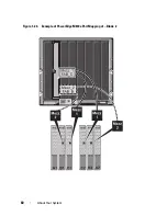
Page 60: ...60 About Your System Figure 1 24 Example of PowerEdge M610x Port Mapping of Blade 2 ...
Page 68: ...68 About Your System Figure 1 26 Example of Half Height Blade Port Mapping ...
Page 136: ...136 About Your System ...
Page 286: ...286 Installing Blade Components ...
Page 308: ...308 Installing Enclosure Components ...
Page 330: ...330 Running System Diagnostics ...
Page 360: ...360 System Board Information ...
Page 362: ...362 Getting Help ...
Page 368: ...Index 368 V video controller installing 273 ...

