236
Installing Blade Components
Installing an Expansion Card
CAUTION:
Many repairs may only be done by a certified service technician. You
should only perform troubleshooting and simple repairs as authorized in your
product documentation, or as directed by the online or telephone service and
support team. Damage due to servicing that is not authorized by Dell is not covered
by your warranty. Read and follow the safety instructions that came with the
product.
1
Unpack the expansion card and prepare it for installation.
For instructions, see the documentation accompanying the card.
2
Open the blade. See "Opening the Blade" on page 159.
3
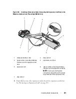
If installed, remove the expansion-card blank:
a
Loosen the captive screw and open the filler-bracket retention latch by
rotating the latch open. See Figure 3-36.
b
Rotate the expansion-card retention latch away from the blank until it
snaps into position under the securing tab. See Figure 3-36.
c
Grasp the expansion-card blank and remove it from the expansion-
card connector. See Figure 3-36.
4
Remove the metal filler bracket out of the blade.
5
Locate the expansion-card connector on the riser.
6
Holding the card by its edges, position the card so that the card-edge
connector aligns with the expansion-card connector.
7
Insert the card-edge connector firmly into the expansion-card connector
until the card is fully seated.
Additionally for NVIDIA M1060 GPGPU card, push the shipping lock up
and snap into place. The shipping lock and the locking tab are installed on
systems installed with a NVIDIA M1060 GPGPU card.
8
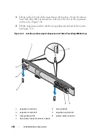
Lift the latch-release tab and rotate the expansion-card retention latch
toward the expansion card. The retention latch holds the full-height
expansion card in position. See Figure 3-36.
9
Close the filler-bracket retention latch and tighten the captive screw. See
Figure 3-36.
Summary of Contents for PowerEdge M620
Page 1: ...Dell PowerEdge Modular Systems Hardware Owner s Manual ...
Page 60: ...60 About Your System Figure 1 24 Example of PowerEdge M610x Port Mapping of Blade 2 ...
Page 68: ...68 About Your System Figure 1 26 Example of Half Height Blade Port Mapping ...
Page 136: ...136 About Your System ...
Page 286: ...286 Installing Blade Components ...
Page 308: ...308 Installing Enclosure Components ...
Page 330: ...330 Running System Diagnostics ...
Page 360: ...360 System Board Information ...
Page 362: ...362 Getting Help ...
Page 368: ...Index 368 V video controller installing 273 ...


