176
Installing Blade Components
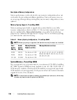
Non-Optimal Memory Configurations
System performance can be affected if your memory configuration does not
conform to the preceding installation guidelines. Your system may issue an
error message during start-up stating that your memory configuration is non-
optimal.
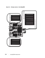
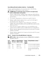
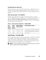
Memory Sparing Support – PowerEdge M915
The memory sparing feature must also be enabled in the
Memory
Information
screen of the System Setup program. See "Memory Settings
Screen" on page 140. To use memory sparing, you must disable node
interleaving.
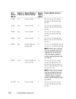
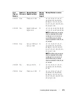
512 GB
Four
Thirty two 16 GB
a
Y
A1, A2, A3, A4, A5, A6, A7,
A8, B1, B2, B3, B4, B5, B6,
B7, B8, C1, C2, C3, C4, C5,
C6, C7, C8, D1, D2, D3, D4,
D5, D6, D7, D8
1 TB
a
Four
Thirty two 32 GB
b
Y
A1, A2, A3, A4, A5, A6, A7,
A8, B1, B2, B3, B4, B5, B6,
B7, B8, C1, C2, C3, C4, C5,
C6, C7, C8, D1, D2, D3, D4,
D5, D6, D7, D8
a
indicates DIMM configurations that operate at 1066 MHz while the rest
of the configurations operate at 1333 MHz.
b
when available
Total
Physical
Memory
Number of
Processors
Memory Modules –
Number and Type
Memory
Sparing
Support
Memory Module Locations
Summary of Contents for PowerEdge M620
Page 1: ...Dell PowerEdge Modular Systems Hardware Owner s Manual ...
Page 60: ...60 About Your System Figure 1 24 Example of PowerEdge M610x Port Mapping of Blade 2 ...
Page 68: ...68 About Your System Figure 1 26 Example of Half Height Blade Port Mapping ...
Page 136: ...136 About Your System ...
Page 286: ...286 Installing Blade Components ...
Page 308: ...308 Installing Enclosure Components ...
Page 330: ...330 Running System Diagnostics ...
Page 360: ...360 System Board Information ...
Page 362: ...362 Getting Help ...
Page 368: ...Index 368 V video controller installing 273 ...

