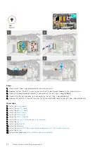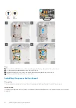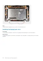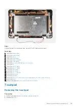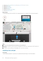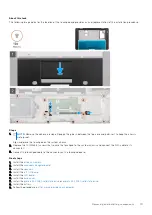
Steps
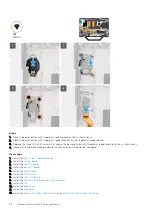
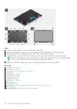
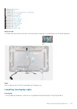
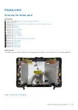
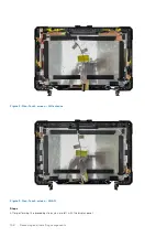
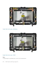
1. Connect the touch cable to its connector on the touch screen board.
2. Connect the eDP cable to its connector on the LCD module and flip the display bezel on the display assembly.
3. Align the display bezel with the display assembly. Gently snap the display bezel into place.
4. In sequential order, replace the 11 (M2.5x6, T8) blue screws that secure the display bezel to the display assembly.
NOTE:
Ensure that the display assembly is placed on a flat surface when replacing the screws to avoid light leakage
from LCD. This must be done when part twisting assembly screw torque: 3 kgf-cm.
5. Replace the 4 (M2.5x6, T8)yellow epoxy screws to secure the display bezel to the display assembly.
Next steps
1. Install the
.
2. Install the
.
3. Install the
4. Install the
.
5. Install the
.
6. Install the
.
7. Install the
8. Install the
.
9. Install the
.
10. Install the
.
11. Install the
.
12. Install the
primary M.2 2280 solid state drive
primary M.2 2230 solid state drive
.
13. Install the
.
after working inside your computer
.
96
Removing and installing components
Summary of Contents for Latitude 5430
Page 19: ...Removing and installing components 19 ...
Page 21: ...Removing and installing components 21 ...
Page 25: ...Removing and installing components 25 ...
Page 31: ...Removing and installing components 31 ...
Page 34: ...34 Removing and installing components ...
Page 69: ...Removing and installing components 69 ...
Page 73: ...Removing and installing components 73 ...
Page 90: ...90 Removing and installing components ...
Page 95: ...Removing and installing components 95 ...
Page 138: ...138 Troubleshooting ...

