NOTE:
Do not over-tighten the heat sink retention screws when installing the heat sink. To prevent over-
tightening, tighten the retention screw until resistance is felt. The screw tension should be not more than 6 in-lb
(6.9 cm-kg).
c) Repeat the procedure for the remaining screws.
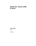
Figure 47. Installing a heat sink (up to 135 W)
1. captive screw (4)
2. heat sink
3. processor socket
4. screw hole (4)
5. To install the 140 W heat sink perform the following steps.
a) Tighten one of the screws (
1
) over
CPU1
to secure the heat sink to the system board.
b) Tighten the screw (
2
) diagonally opposite to the first screw that you tightened.
NOTE:
Do not over-tighten the heat sink retention screws when installing the heat sink. To prevent over-
tightening, tighten the retention screw until resistance is felt. The screw tension should be not more than 6 in-lb
(6.9 cm-kg).
c) Repeat the procedure for the remaining four screws following the order that they are numbered.
Figure 48. Installing the heat sink (140 W)
1. heat sink
2. captive screw (6)
3. processor shield
Installing and removing system components
93