Removing and Installing Parts: Dell Dimension 9200C Service Manual
file:///T|/htdocs/systems/dim9200C/en/SM_EN/parts.htm[10/31/2012 8:07:53 AM]
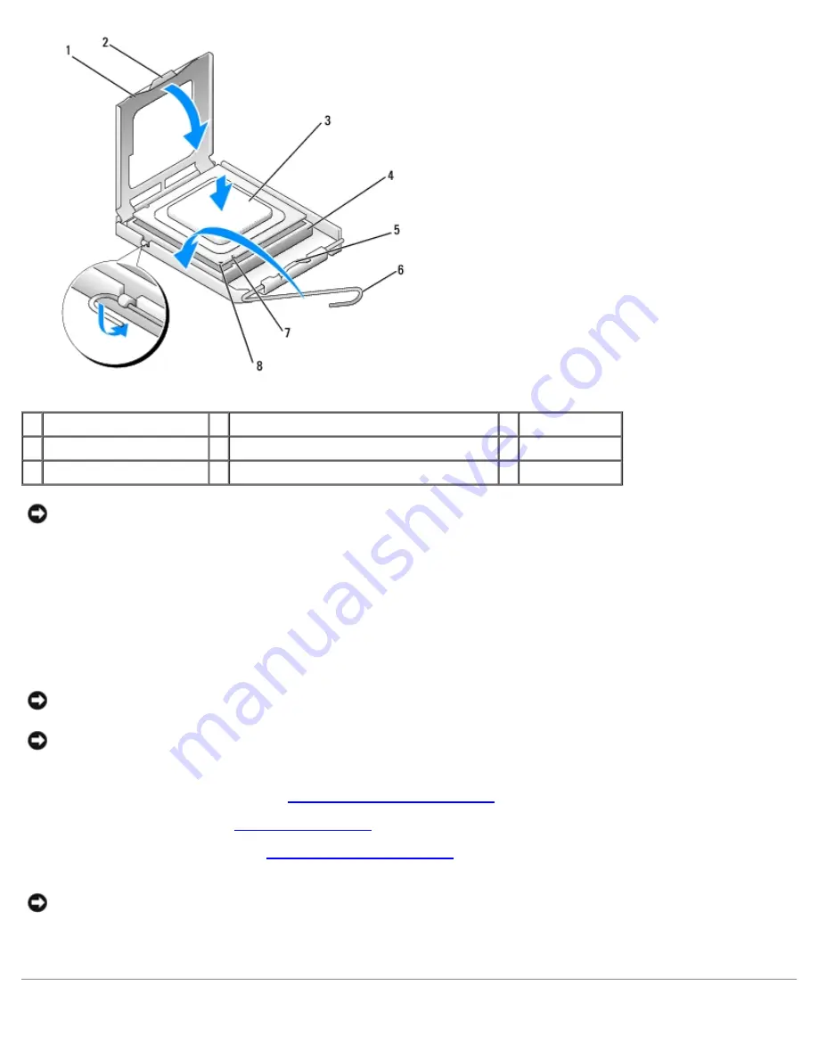
1 processor cover
2 securing tab
3 processor
4 processor socket
5 center cover latch
6 release lever
7 alignment notches (2)
8 socket and processor pin-1 indicator
NOTICE:
Socket pins are delicate. To avoid damage, ensure that the processor is aligned properly with the socket, and
do not use excessive force when you install the processor.
5. Gently place the processor in the socket and check to ensure that the processor is positioned correctly.
6. When the processor is fully seated in the socket, close the processor cover.
Ensure that the securing tab on the processor cover is positioned underneath the center cover latch on the socket.
7. Pivot the socket release lever back toward the socket and snap it into place beneath the securing tab.
NOTICE:
When you install the heat sink assembly, do not touch the thermal interface to prevent damage to the
thermal interface material on the interface.
NOTICE:
If you are
not
installing a processor upgrade kit from Dell, reuse the original heat sink assembly when you
replace the processor. If you installed a processor replacement kit from Dell, return the original heat sink assembly
and processor to Dell in the same package in which your replacement kit was received.
8. Replace the heat sink assembly (see
Installing the Heat Sink Assembly
).
9. Replace the hard drive (see
Installing a Hard Drive
).
10. Replace the computer cover (see
Replacing the Computer Cover
).
NOTICE:
To connect a network cable, first plug the cable into the network port or device and then plug it into the
computer.
11. Connect your computer and devices to electrical outlets, and then turn them on.


