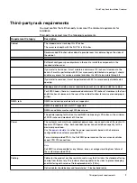
Requirement Category
Description
Cables for third-party components in the rack cannot cross or interfere with ECS
components in such a way that they block front to back air flow or individual FRU service
activity.
Weight
Customer rack and data center floor must be capable of supporting the weight of ECS
equipment.
Use the
to refine the weight requirements based on the
hardware configuration and customer provided cabinet and PDU.
Requesting qualification for non-standard installations
The following scenarios require that you submit an RPQ (Request for Product
Qualification):
l
Installing a single rack ECS solution across multiple racks.
l
Transferring an ECS solution from a Dell EMC rack to a third-party rack.
Organize material
The kits that arrive on site will vary depending on the ECS configuration that you are
installing.
Locate and organize packages, check all components, then move materials next to the
rack where they will be installed.
Components for EX300 systems
Confirm that all components are on site and understand the layout of the rack before
you begin installation.
Component
Description
Back-end (BE) switches for
private network connection
Two Dell EMC S5148F 25 GbE 1U ethernet switches with 48 x 25 GbE SFP ports and 6 x 100
GbE uplink ports
2 x 100 GbE LAG cables per HA pair
Front-end (FE) switches for
customer public network
connection
Two optional Dell EMC S5148F 25 GbE 1U ethernet switches can be obtained for network
connection or the customer can provide their own 10 GbE or 25 GbE HA pair for the front end.
If the customer provides their own front-end switches, they must supply all LAG cables, SFPs,
or external connection cables.
If Dell EMC S5148F 25 GbE front-end switches are used, the 25 GbE ports are configured to
run at 10 GbE to connect to the EX300 nodes, and 2 x 100 GbE LAG cables are provided.
Nodes
Minimum number of nodes per rack is 5 with increments of 1 node up to a maximum of 16
nodes.
Twelve SATA hard disk drives (HDDs) in each node.
EX300 minimum and maximum configurations
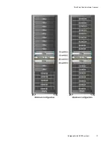
The following diagram represents a 40U rack with the optional service tray installed.
Third Party Rack Installation Overview
12
EX300
Third-Party Rack Installation Guide
Summary of Contents for ECS EX300
Page 1: ...ECS EX300 Third Party Rack Installation Guide 302 005 206 02 ...
Page 6: ...FIGURES 6 EX300 Third Party Rack Installation Guide ...
Page 7: ...Planning your lift 46 1 TABLES EX300 Third Party Rack Installation Guide 7 ...
Page 8: ...TABLES 8 EX300 Third Party Rack Installation Guide ...
Page 13: ...Third Party Rack Installation Overview Components for EX300 systems 13 ...
Page 14: ...Third Party Rack Installation Overview 14 EX300 Third Party Rack Installation Guide ...
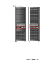
Page 17: ...Figure 1 PDU component location Rail Installation Dell EMC PDU rail and component location 17 ...
Page 42: ...Bring the system online 42 EX300 Third Party Rack Installation Guide ...


