O L I 6 0 0
Operating instructions and warnings
13
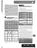
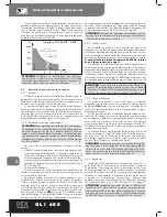
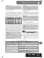
INSTRUCTIONS FOR A CORRECT ADJUSTMENT OF AUTOMATION WITH OLI HYDRAULIC RAM AND
202RR.CONTROL PANEL
(Before proceeding, carefully read the 202RR instructions manual)
When using 202RR control board with Hydraulic ram “OLI 600” series there are two different ways of adjustment, depending on
the type of installation required:
Force adjusted mechanically on ram (More practical and a faster installation):
1. Program the operators force nearly at maximum (P014 = P016 = 99%);
2. Go to parameter P.001, “wing No. 1 positioning” and by pressing “+“button bring the wing into the completely open position. If
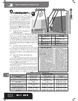
wing does not move, adjust the ram force by adjusting brass screw on the opening exhaust valve, until wing moves smoothly;
3. Now by pressing “-“button bring the wing into the completely closed position. If wing does not move, adjust the ram force by
adjusting brass screw on the closing exhaust valve, until wing moves smoothly;
4. Go to parameter P.002, “wing n°2 positioning”. Continue steps 2 and 3 as per wing n°1;
5. Go to P.003 and start the learning manoeuvre. Motor 1 starts to close and automatically stops once it arrives at the end of stroke.
Motor 2 starts too close and automatically stops once it arrives at the end of stroke (i.e. fully closed (if the operator doesn’t stop,
press OK). display shows “----“: the learning is now completed.
Force electronic adjustment and setting of the obstacles detection device (Higher level of safety, slower instillation):
1. Set the operator force(P014 motor 1) at an intermediate value 50% (Or higher if gates are very heavy);
2. Completly loosen both exhaust valve screws (anticlockwise);
3. Go to P.001, “wing positioning”;
4. Press the “+” button (or CH2 of an already memorized remote): the motor starts up, but the wing doesn’t move. Keeping the
button pressed, close the opening exhaust valve (clockwise) until the motor starts opening with the desired force;
5. Push the “-” button (or CH4 of an already memorized remote): the motor starts up, but the wing doesn’t move. Keeping the
button pressed, close the closing exhaust valve until the motor starts closing with the desired force;
6. Exit from P.001 and get access to P.014: decrease the set force, exit from P.014 and go again to P.001 in order to check that motor
can correctly move the wing in both directions;
7.
Repeat point 6 until you will find the minimum force value that can correctly move the wing in both direc-
tions;
8. Go to P.001 and push the”-“button to bring the wing to fully closed position (ram fully extended) tighten the closing exhaust valve
further on until you hear the pump completely stop and the operator is under stress;
9. Press the “+” key and bring the wing to fully open position (ram is fully in). Keeping the button pressed, tighten the opening
exhaust valve until you hear the pump completely stop and the operator is under stress;
10. Leave the wing completely opened;
11. Repeat all the procedure from point 1 to point 10 for the wing n° 2 using P.002 for the positioning and P.016 to ad just the force.
At last, leave the wing completely opened;
12. Go to P.003 and start the learning manoeuvre. This will automatically conclude when both wings are arrived at the closing stop
and the display shows “----”.the learning is now completed;
When electric lock is fitted, if it has difficulties in latching, during the learning cycle (P003) assist the latch mechanism by pu-
shing the wing with the hands, (until latched) then proceed as follows:
13. Set up P.031 “force in the very last distance” with a value 30% greater than Value of P.014 (e.g.: if P.014 = 50, then P.031 =
65);
14. Start a closing manoeuvre and when wing n°1 arrives at stroke, before the working times finishes, tighten the closing exhaust
valve further on until the electro-lock latches.


