background image

19

1 –

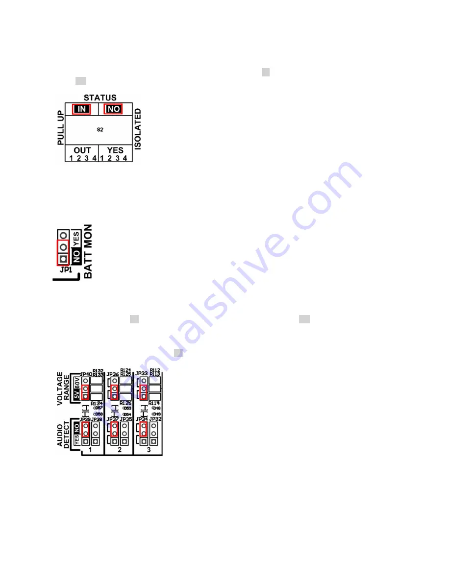
Status input

The status inputs can all be individually set for separate grounds or for internal grounds with pull-up resistors. The

factory default DIP switches position is in the both pull-up mode (IN position on all 4 inputs) and the internal ground

mode (NO position all 4 inputs).

2 –

Battery monitoring

The Metering Input 12 has a jumper (JP1) that allows measurement of the RTC battery voltage when in position

YES.  To display the correct battery voltage, the voltage range of the metering input 12 must be in the 5V position.

Furthermore, the metering input ABC parameters must be set to: A=0, B=1, C=0, D=0 in the input’s configuration

screen.

3 –

Metering input

To configure the metering input in 0-5V or 0-60V voltage range, place the VOLTAGE RANGE jumper in the desired

voltage range position (5V or 60V) and the AUDIO DETECT jumper in the NO position.  By default, the metering

input jumpers are set 0-5V.

If you want to use a metering input as an audio rectifier, place the AUDIO DETECT jumper in the YES position and

the VOLTAGE RANGE jumper in the 5V position.

Summary of Contents for Cortex 320

Page 1: ...emote Site Management System MAN1028 Version 1 0 September 2019 Davicom a division of Comlab Inc 2272 Leon Harmel Quebec QC Canada G1N 4L2 Tel 1 418 682 3380 Fax 1 418 682 8996 w w w d a v i c o m c o m Reference Guide ...

Page 2: ...2 ...

Page 3: ...n risk and agree to fully indemnify Comlab for any damages resulting from such improper use or sale Comlab reserves the right to make design changes to its products without incurring any obligation to make the same changes to previously sold units Safety information The Davicom unit should be installed by qualified technical personnel only Installation of this device by an unqualified person could...

Page 4: ...quipment is operated in a commercial environment This equipment generates uses and can radiate radio frequency energy and if not installed and used in accordance with the instruction manual may cause harmful interference to radio communications Operation of this equipment in a residential area is likely to cause harmful interference in which case the user will be required to correct the interferen...

Page 5: ...5 ...

Page 6: ...vLink 6 via the USB port 24 2 7 1 CONNECTING PHYSICAL I O TO THE CORTEX 360 25 2 7 2 CONNECTING PHYSICAL I O TO THE CORTEX 320 26 3 USER INTERFACE MENUS 28 3 1 USER INTERFACE 28 3 2 MENUS 29 4 UNIT CONFIGURATION AND PROGRAMMING 31 4 1 MENUS AND OPTION ACCESSIBILITY 31 4 2 SYSTEM MENU 31 4 2 1 Administration 32 4 2 2 Alarm Call Lists 33 4 2 3 Date Time and Location 37 4 2 4 IP Configuration 39 4 2 ...

Page 7: ...CE FILES VERSUS CONFIGURATION FILES 86 6 2 PRE LOADED WORKSPACE 86 6 3 EDITING AND CREATING WORKSPACES 86 6 4 WORKSPACE TRANSFERS 88 6 5 SAVING WORKSPACES 89 6 6 LOADING A WORKSPACE 90 6 7 UPLOADING AND DOWNLOADING WORKSPACES TO AND FROM A CORTEX 90 APPENDIX A FACTORY RESET 92 APPENDIX B CONTACT INFORMATION 92 ...

Page 8: ...ual as it becomes available 1 2 What s a Remote Management System Remote management refers to monitoring control and operation of electronic or mechanical equipment located at a remote location from a central station called a NOC Network Operation Center Remote management applications are almost limitless At the core of the remote management process is the Remote Telemetry Unit RTU a device with c...

Page 9: ...9 1 3 Specifications ...

Page 10: ...ws the unit s call out status It will turn on every time the unit makes an outside call telephone email SNMP Trap etc USER ONLINE Indicates if one or more users are connected to the unit ACTIVITY Indicates the health status of the CPU This heartbeat flashes at a rate of one 1 pulse per second when the unit is operating correctly PAUSE and LOCAL buttons The PAUSE button stops transmission of Alarms...

Page 11: ...itor INPUT OUTPUT connectors Two 50 pin connectors CORTEX 360 or 25 pin connectors CORTEX 320 provide interconnection from the unit to the outside world They allow access to the unit s physical inputs and outputs Metering Status Relays They also provide auxiliary supply outputs 5 Volts and 12 Volts for sensors and accessories Audio jacks The first audio jack outputs whatever audio has been selecte...

Page 12: ... SUPPLY INPUT Protection fuse 3 amp fuse protection on power supply inputs DC input power jacks Redundant 4 pin XLR connectors provide power to the unit Any one of the two inputs can be used at any time to power the unit or both at the same time These two power inputs allow for power redundancy The power rating is either 12 VDC 3 Amps OR 24 VDC 1 5 Amps but any voltage between 10 and 30 VDC can be...

Page 13: ... 6 software 1 3 4 Rear panel CORTEX 320 CORTEX 320 Rear Panel Ethernet Port Provides IP access to the unit Expansion modules can also be added to the CORTEX 320 by connecting this port to an external Ethernet switch sold separately USB ports An embedded 2 port USB hub allows connection of USB accessories like memory sticks Davicom Expansion devices or Modbus compatible equipment and accessories IN...

Page 14: ...t to send alarm calls by modem or voice Power Fail P F Monitors the presence of the main AC utility power through the use a small external AC adapter When the voltage derived from the main AC utility power falls below a specific level this input will change level from normal to active It can be set to trigger alarms and advise users that a power outage occurs at the site THIS IS NOT THE UNIT S POW...

Page 15: ...0 to 30 Vdc Current consumption Typically 200 mA 275 mA with all relays energized Typically 300 mA 12 Vdc The Cortex 360 features a dual input system that allows for power supply redundancy two power supplies can be connected at the same time in order to provide automatic fail over switching in case one of the power supplies fails The Cortex uses a 4 pin XLR connector for the power supply male on ...

Page 16: ...16 2 4 Setting Internal Jumpers and DIP Switches 2 4 1 Jumpers for the Cortex 360 Jumpers and switches location on the Cortex 360 main board ...

Page 17: ... grounds with pull up resistors DIP Switches S11 and S12 select isolated grounds mode Default is NO on all 16 inputs DIP switches S9 and S10 select pull up resistor mode it is IN by default on all 16 inputs 3 Metering input The Cortex 360 metering inputs can be configured for 4 20 mA operation To select this mode place the jumper for the desired metering input in the ON position By default the met...

Page 18: ...18 2 4 2 Jumpers for the Cortex 320 Jumpers and switches location on the Cortex 320 main board ...

Page 19: ...ay the correct battery voltage the voltage range of the metering input 12 must be in the 5V position Furthermore the metering input ABC parameters must be set to A 0 B 1 C 0 D 0 in the input s configuration screen 3 Metering input To configure the metering input in 0 5V or 0 60V voltage range place the VOLTAGE RANGE jumper in the desired voltage range position 5V or 60V and the AUDIO DETECT jumper...

Page 20: ... selected metering inputs in the 5V position When the selected inputs are open circuit the metering inputs show approximately 2V High 5 Relays Relays 4 5 and 6 can be SPST Form A or B Place the jumper in NO position to have an SPST Form A relay or in NC position to have an SPST Form B relay By default the three relay jumpers are in NO position 6 Audio IN OUT These two jumpers configure the back pa...

Page 21: ...must re take control manually if you want to resume control 2 6 1 Connecting by IP with your web browser The Cortex factory default IP address is 192 168 1 210 and you can connect to any of the rear panel Ethernet ports 4 on Cortex 360 and 1 on Cortex 320 If this address is not within the address range of your network or computer please refer to your network administrator to change the settings of...

Page 22: ...1 210 unsafe There is no problem with accessing the unit this way The following login screen will show up Enter super01 for the Username and enter ssssssss for the Password See section 4 2 6 for more details on default users and passwords ...

Page 23: ...shboard as shown below the actual dashboard may look different One important difference between the new Cortex family and legacy Davicom units is that the workspaces GUI displays now reside within the unit s memory and not in the user s PC with the DavLink application ...

Page 24: ...nstalled the USB driver please connect your computer to the Cortex s front panel USB port and then start DavLink Once started DavLink will display its main screen Go to the upper left of this screen to see Select Setup Communications and you will see the following screen go to the Local Communications section and select the Communication Port that corresponds to the USB port where you have connect...

Page 25: ... but instead loads it internally from the computer s memory DavLink has been configured this way to allow operation over narrow band data channels like slow satellite links narrowband radio channels or RS 232 multi drop lines 2 7 1 Connecting Physical I O to the Cortex 360 The most convenient way to connect physical I O to the Cortex 360 is through Davicom s MIOP300 screw terminal I O panel This r...

Page 26: ...t importantly to ground the unit with an appropriate ground wire or strap 2 7 2 Connecting Physical I O to the Cortex 320 The most convenient way to connect physical I O to the Cortex 320 is through Davicom s DVIO320 screw terminal I O board This board provides complete connection options for the auxiliary DC outputs 12V and 5V the metering inputs the internal or external ground status inputs as w...

Page 27: ... VDC 2A or open collector 100 mA Depending on your requirements and setup you must also remember to connect the telephone line the Power Fail detector wall wart the network and most importantly to ground the unit with an appropriate ground wire or strap ...

Page 28: ...its or uploaded back to the original unit IMPORTANT In order for the on screen I O boxes and meters to be live showing colors text and measurement values the actual I O s must first be configured Otherwise they will appear as empty or grayed out MORE IMPORTANT The Cortex menus and screens are dynamic meaning they will show more or less items based on a user s access level and if the user is in con...

Page 29: ...tions Pings receive Schedulers timers Commands Flags inputs to receive UUC s or Unit to Unit Commands as well as several others OUTPUTS Everything that is considered or defined as an output is found here Relays Virtual Relays SNMP SET write and Unit to Unit Commands DEVICES This section provides access to the setup of external equipment accessories and I O expansion that can be connected to a Cort...

Page 30: ...may also appear If it doesn t just click on the Gear icon The upper right corner menu shows an general alarm status LED a data download refresh button not to be confused with the web page update button F5 function on the browser two buttons to put the unit into Pause or Local modes an alarm call enable disable button and a button to logout of the unit Your current user level and Control status are...

Page 31: ...ted in the different menus require users to have sufficient access rights the appropriate access level or to be in control of the unit in order for these commands to be available Commands that are not available will show up as grayed out or not appear at all 4 2 System menu The System menu contains settings that are mostly related to the way the unit is accessed how it calls out or how it logs inf...

Page 32: ...ome of the following commands You must be logged on as a Supervisor or higher to see these menu options 1 TAKE CONTROL Allows a user with the proper access rights to take control away from another user 2 UPDATE CERTIFICATE Regenerate the unit s HTTPS certificate Might be required in some situations where a unit s IP address is changed 3 FEATURE KEY Used for installation of paid options such as SNM...

Page 33: ...o automatically perform commands and actions when a problem occurs at the site alarm calls to on duty personnel remain an extremely important feature Understanding alarm calls priorities and sequence The Cortex and the other Davicom units can be programmed so that specific events trigger different alarms Each unit has 16 possible alarm lists composed of 8 Majors 1 through 8 red and 8 Minors 1 thro...

Page 34: ... Setup menu for the selected list s 4 DELETE Erase the content of the selected list s 5 REFRESH READ Refresh read the screen content 6 EXIT Exit menu The Alarm Call List ACL Right Click menu gives access to the setup Config screen but also allows immediate access to temporarily Disable or Enable any list ...

Page 35: ...fined name Available names are CRITICAL MAJOR ALERT SEVERE ERROR WARNING MINOR NOTICE NOTIFICATION INFO INFORMATION This name will appear in the alarm title when received 4 NUMBER ACL number Select the desired ACL number 1 through 8 5 QUALIFIER Lock unlock the ACL based on the status of an input output or flag When the given qualifier is HIGH or ACTIVE or ON the ACL is enabled When the Qualifier i...

Page 36: ...SMS only a cellular modem with is required to send SMS directly from the Cortex 11 READ Read the screen content select the ACL to be read from the top menu ID box 12 UPDATE Update the screen content after changes have been made 13 ERASE Erase or delete any screen content 14 TYPE Type of alarm output Email voice FAX Note that this field will determine what type of information will need to be entere...

Page 37: ...s 5 BEGINS ON Date at which the Daylight Saving Time period begins 6 AUTOMATIC CLOCK SYNCHRONIZATION Set the clock to synchronize automatically on an external time synchronization service 7 PHONE IP ADDRESS Means by which the Automatic Clock Synchronization will take place either by phone internal modem required or by IP 8 SYNC CLOCK AT Daily clock sync time 9 NUMBER OF ATTEMPTS Number of attemps ...

Page 38: ...ST AJUSTMENT when it activates 17 ENDS ON Date at which the Daylight Saving Time period ends switching back to Standard Time 18 CALLOUT DEVICE Physical mean by which the clock synchronization will take place IP Ethernet or phone modem 19 SYNC CLOCK EVERY Number of days between clock synchronizations 20 DELAY BETWEEN ATTEMPTS Amount of wait time between the clock synchronization attemps in the even...

Page 39: ...ection 4 2 4 1 IP Configuration General tab 1 ENABLE DHCP Enable disable the DHCP feature 2 IP ADDRESS IP address of the unit 3 NETMASK Netmask of the unit 4 GATEWAY IP address of a Gateway It is very important to set a gateway otherwise the unit may not communicate successfully with the network 5 DNS SERVER IP address of a Domain Name Server ...

Page 40: ...resh read the screen content 9 SAVE Save the screen content 10 EXIT Exit menu 4 2 4 2 IP Configuration E mail tab 1 UNIT E MAIL ADDRESS Mandatory email address of the unit required by some email servers even if the unit cannot receive email communications Depending on the email server there may be no need for it to be a valid email it only needs to be fomatted as such Examples mountain_top gmail c...

Page 41: ... READ Refresh read the screen content 10 SAVE Save the screen content 11 EXIT Exit menu 4 2 4 3 IP Configuration WEB tab 1 ENABLE WEB SERVER Enable disable the unit s web server CAUTION if the web server is disabled the only means of communicating with the Cortex will be via DavLink 2 HTTP PORT HTTP port number for web access 3 HTTPS SSL PORT HTTPS port number for SSL access Usually port 443 but i...

Page 42: ...isconnect 4 IDLE TIMEOUT This setting is the time in minutes after which the FTP server will disconnect following no activity idle 5 ENABLE ENCRYPTION Enable disable the FTP encryption 6 USE SSL V2 Use SSL version 2 for FTP encryption 7 USE SSL V3 Use SSL version 3 for FTP encryption 8 USE TLS V1 Use TLS version 1 for FTP encryption 9 REFRESH READ Refresh read the screen content 10 SAVE Save the s...

Page 43: ...1 SNMP MODE Selects the types of SNMP actions allowed Traps only Traps and GETs or Traps GETs and SETs 2 SNMP PORT IP port used for SNMP commands Default is 161 but can be changed as required 3 COMMUNITY READ ONLY Name of the community kind of password for the SNMP read only commands GETs 4 COMMUNITY READ WRITE Name of the community for the SNMP read and write commands 5 CORTEX MIB FILE Clicking t...

Page 44: ...D TEST TRAP TO Sends a trap to the device s IP adress specified in this field 12 TEST TRAP Generate a Trap for test purposes 13 REFRESH READ Refresh read the screen content 14 SAVE Save the screen content 15 EXIT Exit menu 4 2 5 System Status View The System Status View is a screen that shows information and overall status of different settings and I O s at the site It shows at a glance the genera...

Page 45: ...that many settings can be edited in Bulk This feature can make configuring much quicker for system administrators When doing bulk editing some setting boxes might show up as grayed out this means that these settings are not available for bulk edition To access any grayed out setting edit users one at a time The table below shows the default users for the system along with their passwords Username ...

Page 46: ...sers 5 REFRESH READ Refresh read the screen content 6 CUSTOM LEVEL EDITOR Access the custom level editor menu to create edit or delete custom access levels 7 ADD Add a new user 8 EXIT Exit menu Once you have selected a user or decided to add one with the you access the User Configuration menu The User Configuration menu allows setting the information for each user 1 REAL NAME Usual name of the use...

Page 47: ...ed for local display of site information in more detail than what is possible on the front panel OLED display It can be used as a simple live site status display or used with a keyboard and mouse connected to the Cortex 360 s USB hub to control site equipment The site information shown on this display is presented in a special dedicated Workspace called the HDMI Workspace It is selected in the Wor...

Page 48: ...eans that the content of the corresponding slot is erased the slot itself always remains Renaming a Workspace slot allows for easier management For example 1W10 can be assigned for use on Andrew s iPhone so it could be called Andrew iPhone some icons may appear greyed out depending on which menu selection you have made 1 WORKSPACES Selects a Workspace slot There are 32 possible Workspace slots in ...

Page 49: ...the Cortex When you press on this button a File Explorer window will open on your computer to allow you to select the file you wish to transfer from your computer 4 EXIT Exit menu The Unit to PC Tab is similar The Transfer button will initiate the download of a zip file to your PC s download folder Note that your web browser may block these downloads so you may have to enable them by clicking on t...

Page 50: ...ng or are greyed out first check if you are still in control or make sure you have proper access level access rights 4 3 1 Generic Input Menus The Cortex inputs have 3 very similar looking menu screens which recur frequently This section provides information on these 3 generic screens They are explained here to avoid repetition but particularities will be mentioned when applicable Most screens ini...

Page 51: ...drop down menu in 2 2 DESCRIPTION RETRIEVAL Click to retrieve and display the current normal description of that ID Normally hidden to minimize data transfers on low speed or high fee data connections 3 DEFAULT ACTIVE DESCRIPTION Description of the input when it is active alarm condition Up to 68 charaters are allowed Examples High indoor temperature Low fuel level Door is open Smoke High water le...

Page 52: ...inputs with identical or closely matching settings it is possible to copy the settings from an input and paste it into another input saving configuration time and minimizing possible typing errors First select the source input ID from the menu then click the Refresh Read button 9 then go select the destination input ID from the menu and click the Save Write button 10 10 SAVE WRITE Save the screen ...

Page 53: ...e main screen will reappear actual content will differ from what is shown here In this screen inputs can be added deleted or edited All inputs that have been added will appear in the list To edit an input right click anywhere on the desired input line To exit this menu click on the exit button 11 1 SELECT ALL Select unselect all boxes at once for bulk editing 2 STATE Current state of the inputs no...

Page 54: ...d the screen content 10 ADD Add an input 11 EXIT Exit menu 4 3 2 AC Power Fail and boot flags The AC Power Fail input provides a way to monitor the main AC utility power through small wallwart power supply included with your Cortex unit If the utility power fails the input becomes active and an alarm can be generated if it has been so configured The AC Power fail input is associated with the flag ...

Page 55: ...both physical and virtual and SNMP SETs For the relays adding a P suffix will Pulse the relay ex 1R01P L will Latch it and R will Release it 6 DELAY BEFORE ACTION Delay before the input changes into an active state when an out of limit condition occurs Prevents glitches from setting off any alarms 7 DELAY BEFORE RETURN TO NORMAL Delay before the input returns to a normal state once an out of limit...

Page 56: ...ajor 3 ID ID of the inputs 4 DESCRIPTION Description of the inputs Factory suggested descriptions but modifiable by user 5 VALUE Shows current value of the inputs 6 INDIVIDUAL SELECTION Select unselect one or more inputs 7 CONFIGURATION Brings up the configuration menu of the selected inputs Bulk edition is allowed see at the beginning of this section for more details Menu can also be directly acc...

Page 57: ... input will be monitored and be able to generate alarms When the qualifier is non active or normal the input will be muted and it will not be able to generate an alarm To invert the Qualifier s level simply put a in front of its ID For example use 1D01 to invert it Leave the Qualifier field blank for a don t care condition STATE default setting the State Normal or Active of the input being qualifi...

Page 58: ...eration 12 QUALIFIER STATE or DATA 13 MEASUREMENT UNIT Select desired measurement unit or enter your own Maximum of 3 characters 14 HYSTERESIS HIGH LIMIT Gap value which must be exceeded when the input voltage returns from a high out of range state before the input can actually switch back to a normal state 15 HYSTERESIS LOW LIMIT Gap value which must be exceeded when the input voltage returns fro...

Page 59: ...ection pseudo RMS an also for 4 20mA modes Please see Section 4 3 1 for details about the generic Main screen Description screen and Vocal Description screen 1 ID ID of the selected input Select from the drop down menu 2 I O DESCRIPTION RETRIEVAL Click to retrieve and display the current normal description of that ID Normally hidden to minimize data transfers on low speed or high fee data connecti...

Page 60: ...lse or nuisance alarms while still being in full control of the transmission site Multiplier can be any number between 0 and 9999 10 DELAY BEFORE ACTION Delay before the input changes into an active state when an out of limit condition occurs Prevents glitches from setting off any alarms 11 DELAY BEFORE RETURN TO NORMAL Delay before the input returns to a normal state once an out of limit conditio...

Page 61: ...n unchecked no alarm will be triggered when an out of limit condition occurs 22 SIGNALLING ON RETURN TO NORMAL Enables disables Return To Normal signalling When checked a notification will be generated when the input changes back to its normal state after an out of limit alarm condition When unchecked no notification will be sent when the initial alarm condition returns to normal 23 SYSTEM LOG Log...

Page 62: ...sfer on low speed or high fee data connections 3 ACTION TYPE Selects the action type that will happen when an out of limit condition occurs 3 types are available Major alarm Minor alarm and Command CMD On CMD no alarm will be triggered Use this Action when you want to take actions without triggering any alarms 4 QUALIFIER Qualifying element operand which can be any input output flag timer SNMP GET...

Page 63: ...RETURN TO NORMAL Enables disables Return To Normal signalling When checked a notification will be generated when the input changes back to its normal state after an out of limit alarm condition When unchecked no notification will be sent when the initial alarm condition returns to normal 14 REFRESH READ Refresh read the screen content 15 SAVE WRITE Save the screen content 16 EXIT Exit menu QUICK A...

Page 64: ...bout the generic Main screen Description screen and Vocal Description screen 1 SELECT ALL Select unselect all inputs at once 2 STATE Current state of the inputs normal active minor major 3 ID ID of the inputs 4 DESCRIPTION Description of the inputs 5 VALUE Shows current value of the inputs either High H or low L 6 CONFIGURATION Access the configuration menu of the selected inputs Bulk edition is a...

Page 65: ...e qualifier is non active or normal the input will be muted and it will not be able to generate an alarm To invert the Qualifier s level simply put a in front of its ID For example use 1D01 to invert it Leave the Qualifier field blank for a don t care condition 5 CONTROLLED OUTPUT Outputs to be controlled on off based on the state of this input The two output types allowed are relays both physical...

Page 66: ... limit alarm condition When unchecked no notification will be sent when the initial alarm condition returns to normal 13 REFRESH READ Refresh read the screen content 14 ACTIVITY MONITORING Access the Activity Monitoring menu See next section for details 15 SAVE WRITE Save the screen content 16 EXIT Exit menu 4 3 8 Activity Monitoring This general menu is used to configured the monitoring of any in...

Page 67: ...allowed are relays both physical and virtual and SNMP SETs For the relays adding a P suffix will Pulse the relay ex 1R01P L will Latch it and R will Release it 7 ALARM MODE CONSECUTIVE or CUMULATIVE Method used for the time based activity inactivity alarms of the Status inputs The calculation method takes into account the Maximum Activity Time value and or Maximum Inactivity Time value see 7 and 8...

Page 68: ...he current normal description of that ID Normally hidden to minimize data transfers on low speed or high fee data connections 3 ACTION TYPE Selects the action type that will happen when an out of limit condition occurs 3 types are available Major alarm Minor alarm and Command CMD On CMD no alarm will be triggered Use this Action when you want to take actions without triggering any alarms 4 QUALIFI...

Page 69: ...input s activity in the System Log Useful when inputs do not need to be logged but are required for day to day operation 11 QUALIFIER STATE or DATA STATE default setting the State Normal or Active of the input being qualified can change only when the Qualifier is active Readings from the input Current Value continue to be updated periodically independently from the Qualifier state DATA Same as the...

Page 70: ... no automatic action will happen 3 LOG DAILY ACTIVE TIME Log the daily active time in the System Log 4 RESET COUNTER Manual counter reset 5 RESET AT MIDNIGHT Reset counter at midnight every day 6 RESET TRIGGER Operand based automatic reset Reset can be generated automatically by any input ID in the Cortex 7 LAST RESET Date and time at which the last reset occurred 8 REFRESH READ Refresh read the s...

Page 71: ...O State LED Each virtual logic gate is set individually according to its use and function but one of the most important characteristics of VLGs is that they can be cascaded and nested VLGs allow you to program Davicom units so they act according to y our needs For example you may not want the Davicom to call you during the night to tell you that the utility power is off and the Generator is runnin...

Page 72: ...D in the Cortex can be used to mute or unmute the input to prevent it from taking any action When the Qualifier is active the input will be monitored and be able to generate alarms When the qualifier is non active or normal the input will be muted and it will not be able to generate an alarm To invert the Qualifier s level simply put a in front of its ID For example use 1D01 to invert it Leave the...

Page 73: ... losing all its settings when the input is causing intermittent problems or nuisance alarms 11 SYSTEM LOG Log the input s activity in the System Log Useful when inputs do not need to be logged but are required for day to day operation 12 TRUTH TABLE Dynamic table showing the logic state Result of the VLG for every possible condition of its operands 1 to 5 Normal is comparable to a logic low or log...

Page 74: ...ires external relays Please see Section 4 3 1 for details about the generic Main screen Description screen and Vocal Description screen 1 ID ID of the selected input Select from the drop down menu 2 I O DESCRIPTION RETRIEVAL Click to retrieve and display the current normal or active description Normally hidden to minimize data transfers on low speed or high fee data connections 3 OPERATING MODE Se...

Page 75: ... REFRESH READ Refresh read the screen content 10 SAVE WRITE Save the screen content 11 EXIT Exit menu RELAY QUICK ACCESS MENU A quick access menu is available by right clicking on any relay line in the main relay menu screen This quick access menu offers manual commands that are only available here like Force On Force Off Release and Pulse 1 CONFIG Access the configuration menu of the selected rel...

Page 76: ...an intervention FOLLOW LATCH This operating mode only allows a relay to be controlled either as a follower or as a latching relay Follow Relay activation follows the state of the input that controls it Latch Relay activates and stay activated for as long as a Release command manual or automatic is not sent by the input that controls it PULSE ONLY This operating mode only allows a relay to pulse It...

Page 77: ... be considered When a relay is controlled by one or more inputs the relay s operating mode may not be changed other than by deleting the relay from every input that controls it then changing the relay mode and finally reassigning the relay to the controlling inputs Therefore when controlling relays from inputs always begin by setting the relay s operating mode according to system requirements and ...

Page 78: ...t can be used to transform non SNMP readings from legacy devices into SNMP compatible data that can be used by the remote SNMP management system The Cortex s SNMP MIB is available for download directly from the unit under the SNMP Agent Tab in the System IP Configuration menu 5 1 1 SNMP GET The SNMP GET inputs are used to process and measure readings obtained digitally by IP from SNMP enabled equi...

Page 79: ...he SNMP used Must be the same version as the one used in the polled equipment 6 QUALIFIER Qualifying element operand which can be any input output flag timer SNMP GET Logic Gate etc Essentially any ID in the Cortex can be used to mute or unmute the input to prevent it from taking any action When the Qualifier is active the input will be unlocked and function normally When the qualifier is non acti...

Page 80: ...se the Level 2 menu Same as Level 1 19 ENABLE Enable disable the input Useful to deactivate an input without losing all its settings when the input is causing intermittent problems or nuisance alarms 20 PORT SNMP IP port number of selected SNMP GET input Default is 161 21 VALUE TYPE Type of value to be read polled from the equipment Different types are available like Integer Display String Gauge T...

Page 81: ... but are required for day to day operation 29 HYSTERESIS LOW LIMIT Gap value which must be exceeded when the input voltage returns from a low out of range state before the input can actually switch back to a normal state 30 HYSTERESIS HIGH LIMIT Gap value which must be exceeded when the input voltage returns from a high out of range state before the input can actually switch back to a normal state...

Page 82: ... generate an alarm see 14 in the menu screen below in order to advise users that a particular SET command did not attain its destination Please see Section 4 3 14 3 for the details about the generic Main screen Description screen and Vocal Description screen 1 ID ID of the selected SNMP SET output Select from the drop down menu 2 I O DESCRIPTION RETREIVAL Click to retrieve and display the current ...

Page 83: ...ay String Gauge Truth Value etc This value type must match the one of the device s controlled I O 12 COMMUNITY SNMP community name Must be an exactly match of the community name set in the remote SNMP device 13 SYSTEM LOG Log the input s activity in the System Log Useful when outputs do not need to be logged but are required for day to day operation 14 SIGNALING ON FAILURE Generate alarm upon SNMP...

Page 84: ...ations it may be required to send only one value or the other but not to have the SET follow the input that controls it For these situations a specific suffix letter can be used to tell the Cortex which value to send This is illustrated in lines B and C of the image below Suffix A for Active will only allow the active value to be sent when the controlling input toggles into an active state while t...

Page 85: ...le to have a specific value sent by entering only one value instead of two in the configuration menu of the SNMP SET output as seen below for example The Cortex gives you practically unlimited flexibility to control other devices ...

Page 86: ...e previous generation of products Workspaces can now reside in the Cortex unit itself This feature not only eliminates the obligation of managing workspace sharing among users of a unit but it also allows any authorized user to connect and have a readily available workspace that can be matched to his requirements It is nevertheless strongly suggested to make backup copies of workspaces and unit co...

Page 87: ...ll appear This menu contains the tools you need to built workspaces Once you have added an object right click on it and then open the Object Edit menu You can then complete the fields as required the most important one being the ID field where you must enter the Input ID of the reading in the Cortex that you wish to connect to this graphic object ...

Page 88: ...h Cortex units and customizing a Workspace the Workspace itself will reside within the Web Browser s active memory or in DavLink if you aren t using a browser This is the live view you see when connected to a Cortex or editing a Workspace You can save workspaces to your computer s disk drive HDD or SSD for archiving and eventual transfer to a Cortex You can also load a workspace from your computer...

Page 89: ...isible activate it with the Gear Icon on the Edit Menu This Save to PC function is actually a Browser download function and will automatically download a file called default dvw to your PC s download location If you wish to change this location you can do so in your browser settings For example in Chrome At the top right clink on the 3 dots Click on Settings At the bottom click Advanced Under the ...

Page 90: ...w Workspace will be added as new Tabs in the browser s display After being asked if you wish to merge your Workspace you will be asked to select the file that you wish to open from your computer s file browser Select the file and it will then be loaded into the browser for display 6 7 Uploading and Downloading Workspaces to and from a Cortex The System Workspaces drop down menu has previously been...

Page 91: ...91 ...

Page 92: ... blue LED s light up At this point press the LOCAL button until the activity LED blinks rapidly 3 Press the Local button repeatedly to toggle between communication user online and activity LED s and stop when the communication LED is on At this point press the PAUSE button to start the factory reset The LOCAL LED will blink for a few seconds to confirm the reset operation has succeeded Appendix B ...

Reviews: