vPad-A1 OPERATORS MANUAL
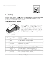
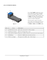
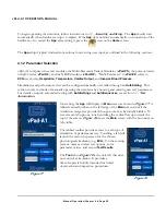
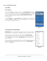
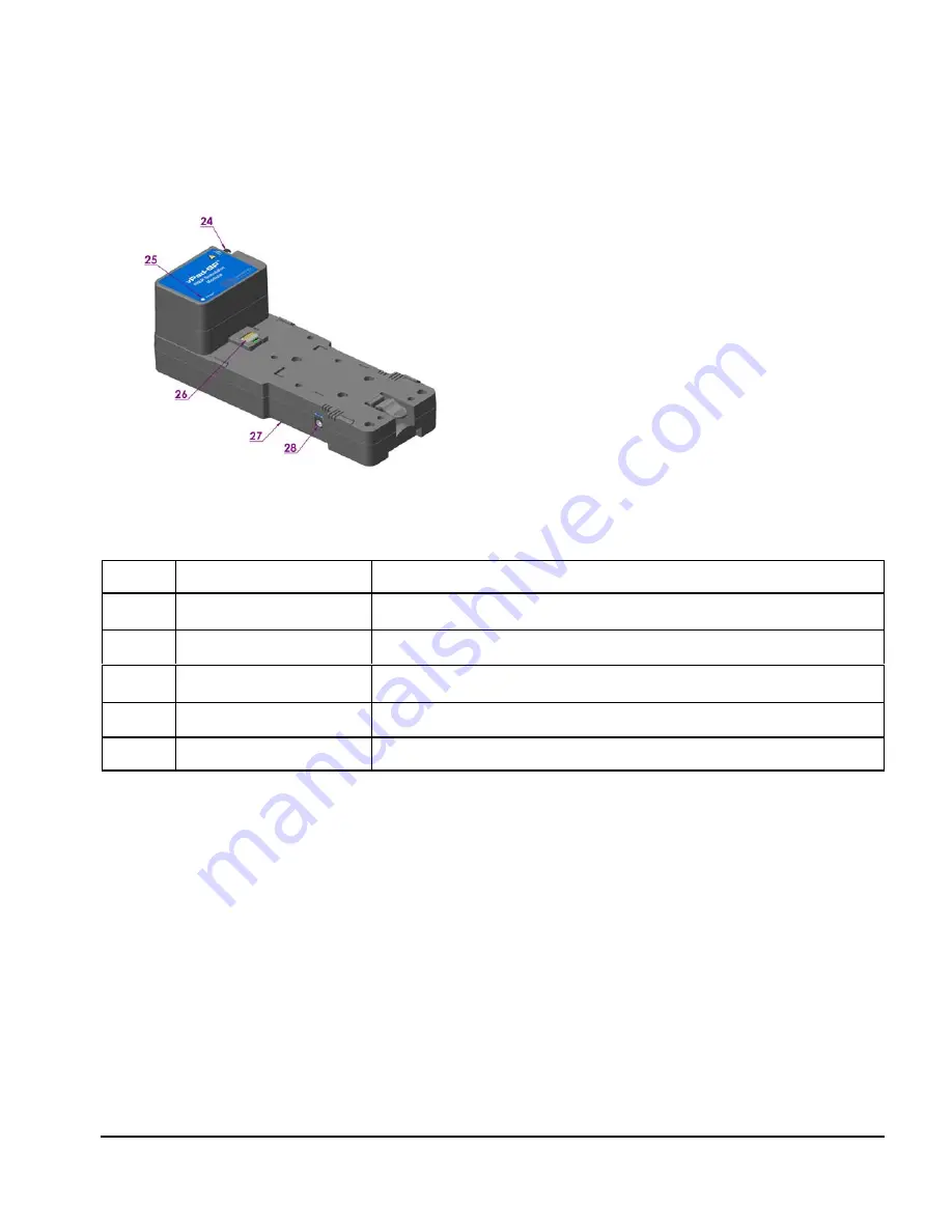
Figure 4
The vPad-BP (
NIBP
) module draws power
from an internal set of three rechargeable
batteries. The module’s operation can be
controlled through a direct connection with
the
Base
, or by means of a pass-through
connection in the vPad-PS module when
used in the stacked configuration.
With all modules stacked, a single DC
power supply can simultaneously charge all
batteries in the system, including those in
the
Tablet
, the
Base
, and the
NIBP
module.
Item
Name
Description
24
NIBP Cuff Connector
Pneumatic connection for cuff hose adapter
25
LED Power Indicator
Power and charge/battery status
26
Power/Data Connector
6 pin inter-module connector for power and serial communications
27
NIBP Reset
Access to NIBP module reset button (bottom)
28
DC Power Supply
Connection for NIBP + Base + Tablet charger
Setup/Chapter 3
#
Page 22
Summary of Contents for vPad-A1
Page 1: ...Operating Manual MN 103c vPad A1 All in One Patient Simulator and Performance Tester ...
Page 2: ......
Page 4: ......
Page 8: ...Page iv ...
Page 14: ...vPad A1 OPERATORS MANUAL Definitions Page x ...
Page 28: ...vPad A1 OPERATORS MANUAL Specifications Chapter 1 Page 14 ...
Page 32: ...vPad A1 OPERATORS MANUAL Overview Chapter 2 Page 18 ...
Page 102: ...vPad A1 OPERATORS MANUAL Automation and Test Records Chapter 5 Page 88 ...
Page 104: ...vPad A1 OPERATORS MANUAL Maintenance Chapter 6 Page 90 ...
Page 107: ...vPad A1 OPERATORS MANUAL Appendix A Page 93 ...
Page 108: ......

