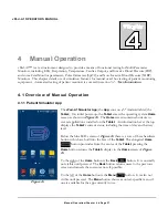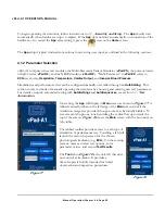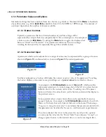
vPad-A1 OPERATORS MANUAL
Figure 1
3
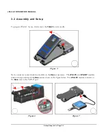
Setup
vPad-A1 is a modular system having a
Base
and one, two or three additional modules which provide patient
simulation or monitor testing. This chapter describes the modules and their connector interfaces, and
provides instructions for assembly and setup of the system.
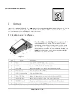
3.1 Modules and Interfaces
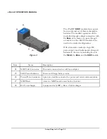
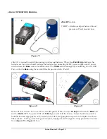
The vPad-A1
Base
module (
Figure 1
) is comprised of a 5"
Android
Tablet
and its cradle. The cradle incorporates a
rechargeable battery which provides power to itself and to
other modules of the system, as well as a communication
hub to facilitate control of the test/simulation modules. The
Tablet
also has a battery, which can be recharged through
the USB connection to the cradle.
Item
Name
Description
1
Tablet
Android 5" color LCD tablet with touch screen
2
Cradle
Snap-in cradle/holder for Android Controller
3
SPO2 Port
miniDIN8 connector to vPad-O2 (SpO2) accessory module
4
Power Switch
Power On/Off for all modules
5
LED Power Indicator
Power and Battery status
6
Tablet USB Port
Battery charging and data input to Android tablet (microUSB)
7
Cradle USB Port
Battery charging and data output from cradle (microUSB)
8
DACOM Port x 2
Proprietary serial data connection to other Datrend vPad products
9
Battery Cover
Locks the battery into the GUI (base bottom)
Setup/Chapter 3
#
Page 19
Summary of Contents for vPad-A1
Page 1: ...Operating Manual MN 103c vPad A1 All in One Patient Simulator and Performance Tester ...
Page 2: ......
Page 4: ......
Page 8: ...Page iv ...
Page 14: ...vPad A1 OPERATORS MANUAL Definitions Page x ...
Page 28: ...vPad A1 OPERATORS MANUAL Specifications Chapter 1 Page 14 ...
Page 32: ...vPad A1 OPERATORS MANUAL Overview Chapter 2 Page 18 ...
Page 102: ...vPad A1 OPERATORS MANUAL Automation and Test Records Chapter 5 Page 88 ...
Page 104: ...vPad A1 OPERATORS MANUAL Maintenance Chapter 6 Page 90 ...
Page 107: ...vPad A1 OPERATORS MANUAL Appendix A Page 93 ...
Page 108: ......

