2 Theory of Operation
2-22
05/04 1006-0453-000
Drive pressure limit switch
The drive pressure limit switch, found on the SIB, is used to monitor the drive
gas pressure from the ventilator pneumatic engine. This normally closed
switch signal is sent to the Aestiva 7900 Ventilator CPU board. The switch will
open if the drive gas pressure is more than 104 +5/-4 cm H2O. The activation
of the switch will stop mechanical ventilation, stop the flow valve drive circuit,
and close the gas inlet valve.
Chassis ground connection
The shell of the 50-pin connector is a continuation of the machine chassis. It
supplies the connection to the SIB shielding box. A mounting hole on the SIB
is attached to the shell of the 50-pin connector and to the SIB shielding box. A
27.4K ohm resistor in parallel with a 0.01 mF capacitor supplies a DC and AC
path to chassis ground for the SIB signal ground.
Inspiratory and expiratory flow measurement
Differential pressure levels in the range of -3.5 cm H2O to +3.5 cm H2O are
applied to the differential pressure transducers by the flow of gasses past the
variable orifice in the flow sensor. This gives DC output voltages in the range of
0.3V to 3.8V, with zero pressure producing 2.05V. The output of the pressure
transducers are buffered with an OPAMP in the same manner as the patient
airway pressure transducer.
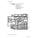
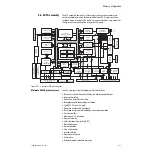
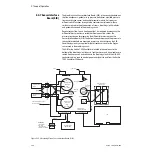
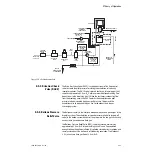
The block diagram shows the pneumatic and electrical connections to the
variable orifice flow sensors. Calibration data for the flow sensor is stored in
an EEPROM in each of the sensors. When directed by system software, a logic
1 enable signal turns on 5 VDC power to the EEPROM. A differential clock
signal is sent to the SIB where it is transformed into a single ended clock by
the MAX488 for the EEPROMs. The EEPROM data lines are open drain signals,
one for each EEPROM. When the data has been read by the Aestiva 7900
Ventilator CPU board, the power and signals are turned off. This helps to
protect the EEPROM data when the flow sensors are plugged and unplugged
from the system while it is in operation. The signals and power supply to the
flow sensor EEPROMs are filtered for EMI immunity and protected against
ESD.
Other connections
The SIB is used as a connection point for the different switches that show the
state of moveable elements within the breathing circuit. The connections are
made using the 26-pin high density connector, which is also used to connect
to the flow sensors. The switches include:
• Canister release
• Absorber bypass
• Bag to vent
• Control panel cover micro switches
• Four optical switch signals from the circuit module identification board
There is a 3-pin connector for the connection of the optional ACGO switch. All
of the switch signals are filtered for EMI immunity and protected against ESD.
Summary of Contents for Aestiva 7900 SmartVent
Page 1: ...Aestiva 5 7900 Anesthesia Ventilator Technical Reference Manual ...
Page 44: ...Notes 2 28 05 04 1006 0453 000 ...
Page 82: ...Notes 4a 36 05 04 1006 0453 000 ...
Page 116: ...Notes 4b 34 05 04 1006 0453 000 ...
Page 150: ...Notes 5 34 05 04 1006 0453 000 ...
Page 158: ...Notes 6 8 05 04 1006 0453 000 ...
Page 182: ...Notes 7 24 05 04 1006 0453 000 ...
Page 202: ...Notes 8 20 05 04 1006 0453 000 ...
Page 203: ......

