5 Troubleshooting
1006-0453-000 05/04
5-31
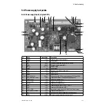
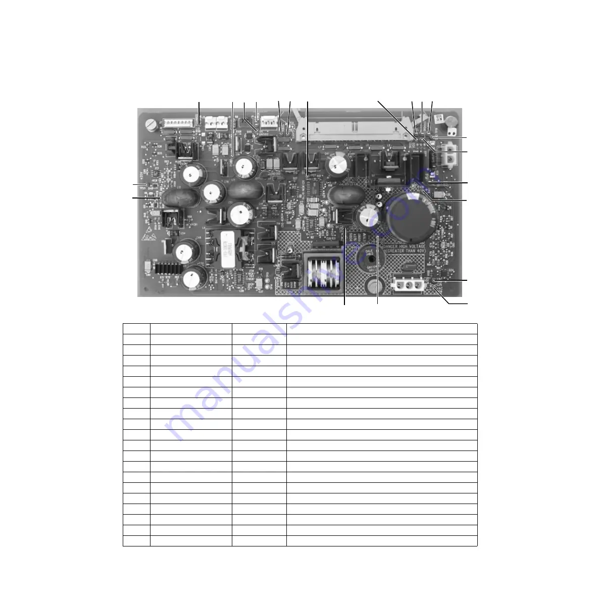
5.6 Power supply test points
5.6.1 Power supply board (original CPU)
TP
Name
Typical Value
Description
1
VBOOT
+15V
Supply to power primary regulator
4
PGND
0V
Power ground
7
VIN
+ 50V
Rectified voltage from transformer (30-60 Vdc)
8
VBUS
+16.5V
Primary regulator output (±5%)
9
BATT_P
+13.3 V
Battery voltage
11
PGND
0V
Power ground
12
VB
+16V
Power bus from VBUS or battery (±5%)
15
DGND
0V
Digital Ground
16
DGND
0V
Digital Ground
17/18
VAC (1)/VAC (2)
35 Vac
AC from toroid (24-45 Vac); measured across TP17 and TP18
19
5R5_VAUX (+5.5–5.8V)
+5.6V
Supply for inlet valve, flow valve, and speaker (±5%)
20
VAN15 (-15V)
-15V
Analog -15V supply (±5%)
21
VAP15 (+15V)
+15V
15V supply (±5%)
22
VH_EL
+14.5V
Supply for EL display (±5%)
23
VDD
+5.0V
Supply for digital circuit (+3.68%, -3.05%)
24
VSW
+15V
Supply for VDD Fail Buzzer (±10%)
25
TP25 (+20V)
+20V
Intermediate supply stage before NOSS (task lights) output
26
P15V_NOSS (+12VLP)
+12V
Supply for task lights (±5%)
27
VB
+16V
Power bus from VBUS or battery (not short protected)
28
VBUS
+16.5V
Primary regulator output (not short protected)
25
12
20
24
8
4
9
21
22
23
16
19
7
28
11
26
1
27
15
18
17
Summary of Contents for Aestiva 7900 SmartVent
Page 1: ...Aestiva 5 7900 Anesthesia Ventilator Technical Reference Manual ...
Page 44: ...Notes 2 28 05 04 1006 0453 000 ...
Page 82: ...Notes 4a 36 05 04 1006 0453 000 ...
Page 116: ...Notes 4b 34 05 04 1006 0453 000 ...
Page 150: ...Notes 5 34 05 04 1006 0453 000 ...
Page 158: ...Notes 6 8 05 04 1006 0453 000 ...
Page 182: ...Notes 7 24 05 04 1006 0453 000 ...
Page 202: ...Notes 8 20 05 04 1006 0453 000 ...
Page 203: ......

