


Appendix D
Cable Replacement Procedure
Page D-3
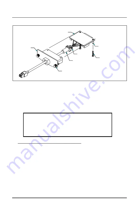
CASE
GROMMET
TIE-WRAP
PCB MOUNT SCREW (2)
THREADED SPACER (2)
INSTALLATION JACK SCREW (2)
PCB
CASE
GROMMET
TIE-WRAP
PCB MOUNT SCREW (2)
THREADED SPACER (2)
INSTALLATION JACK SCREW (2)
PCB
CASE
PCB
THREADED SPACER (2)
TIE-WRAP
GROMMET
INSTALLATION JACK SCREW (2)
PCB MOUNT SCREW (2)
CASE
GROMMET
TIE-WRAP
PCB MOUNT SCREW (2)
THREADED SPACER (2)
INSTALLATION JACK SCREW (2)
PCB
CASE
GROMMET
TIE-WRAP
PCB MOUNT SCREW (2)
THREADED SPACER (2)
INSTALLATION JACK SCREW (2)
PCB
CASE
PCB
THREADED SPACER (2)
TIE-WRAP
GROMMET
INSTALLATION JACK SCREW (2)
PCB MOUNT SCREW (2)
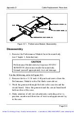
Figure D-1. Performance Module Disassembly
Disassembly
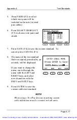
1.
Remove the Performance Module from the main body
(see Chapter 1, Introduction).
CAUTION
Performance Module removal exposes STATIC
SENSITIVE electronics inside the main body.
Ground yourself appropriately to avoid damage.
For the following, refer to Figure D-1:
2.
Remove the two 11/16 inch 4-40 pan head screws from the
Performance Module with a flat blade screwdriver.
3.
Work the grommet through the hole in the case toward the
circuit board. Move the grommet and the circuit board until
both are free of the case.
4.
Make notation of old wire attachments, including color vs.
position, number and direction of twists and approximate lay
in the case.
Artisan Technology Group - Quality Instrumentation ... Guaranteed | (888) 88-SOURCE | www.artisantg.com


