Analog Inputs
Terminals 53 and 54 are the standard analog input
terminals. Each terminal can be configured as a voltage
input or a current input. Switch S201 on the control card is
used to configure terminal 53 and switch S202 is used to
configure terminal 54.
Use
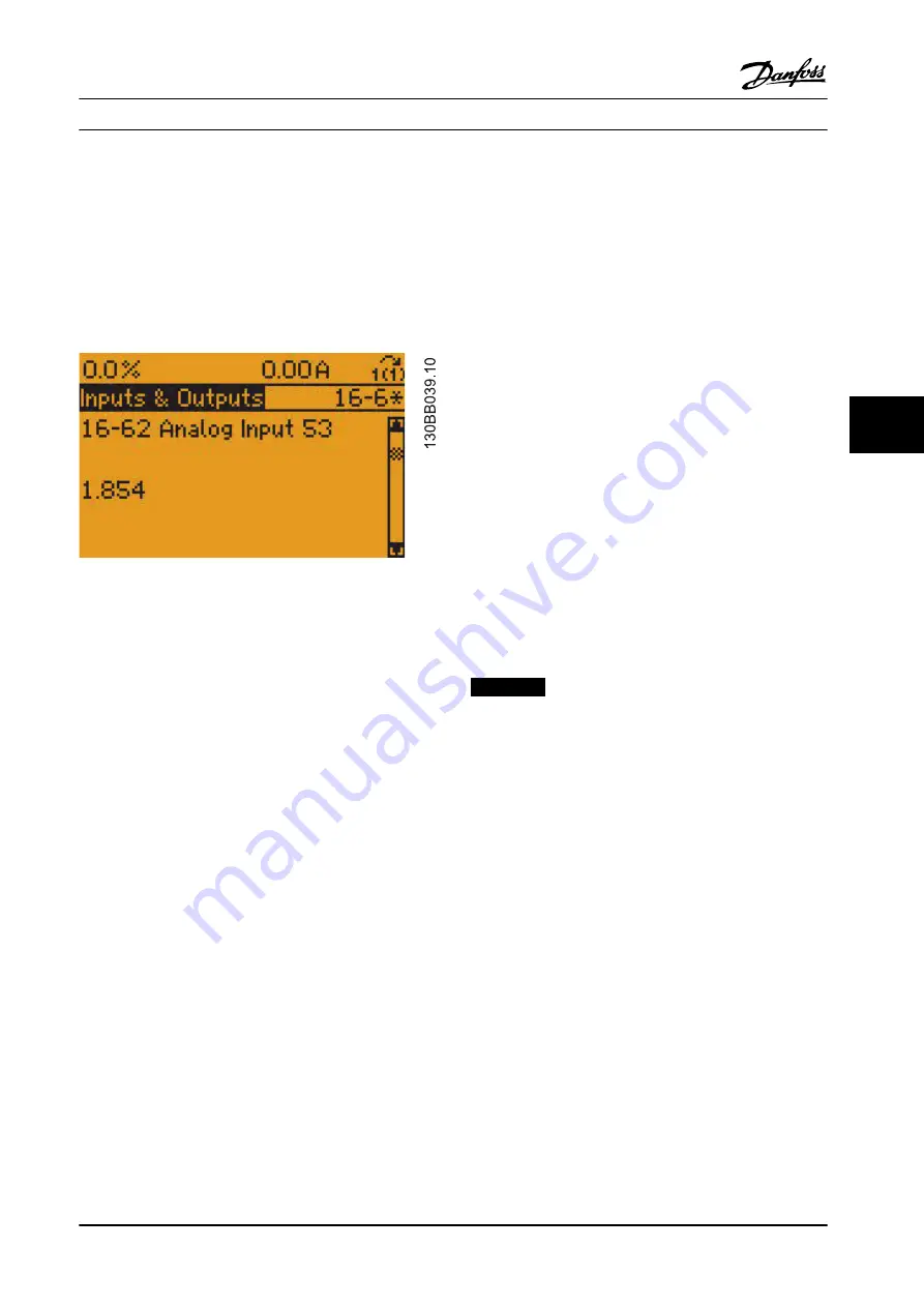
16-62 Analog Input 53
to display the value on terminal
53 and
16-64 Analog Input 54
to display the value on
terminal 54.
Figure 6.13 Analog Inputs Display
Problems in the external control wiring to the adjustable
frequency drive, configuration of the switches, or a faulty
control card cause an incorrect signal to display.
The power for the analog inputs can either come from the
power supply built into the adjustable frequency drive, or
from an external power supply. If an external power supply
is used, the common of the supply must be referenced to
terminal 55.
Verify the control voltage power supply.
1.
Connect the (-) negative meter lead to terminal
55.
2.
Connect the (+) positive meter lead to terminal
50.
The correct reading is 9.2–11.2 V DC. If the power supply
voltage is not present, perform the basic control card
voltage test.
Verify that the analog input is configured for the type of
signal being sent to the adjustable frequency drive.
16-61 Terminal 53 Switch Setting
shows the configuration of
terminal 53, and
16-63 Terminal 54 Switch Setting
shows the
configuration of terminal 54. If the inputs are not
configured correctly, power down the adjustable frequency
drive and change switches S201 and S202.
Check the individual inputs if configured for voltage.
Measure the DC voltage as follows:
1.
Connect the (-) negative meter lead to terminal
55.
2.
Connect the (+) positive meter lead to terminal
53 or 54.
For each analog input, the measured DC voltage should
match the value shown in the display parameter. If the
display does not correspond with the measured input and
the switch is configured for voltage, the analog input on
the control card has failed. Replace the control card.
Check the individual inputs if configured for current.
Measure the DC voltage as follows:
1.
Connect the (-) negative meter lead to terminal
55.
2.
Connect the (+) positive meter lead to terminal
53 or 54.
When configured for current, the current flows through a
200
Ω
resistor to create a voltage drop. A 4 mA current
flow creates approximately a 0.8 V DC voltage reading. A
20 mA current flow creates approximately a 4.0 V DC
voltage reading. The display shows the mA value. If the
display does not correspond with the measured input, the
analog input on the control card has failed. Replace the
control card.
NOTICE!
A negative voltage reading indicates a reversed polarity.
Reverse the wiring to the analog input.
6.5 After Repair Tests
Following any repair to an adjustable frequency drive or
testing of an adjustable frequency drive suspected of
being faulty, the following procedure must be followed.
Following the procedure ensures that all circuitry in the
adjustable frequency drive is functioning properly before
putting the unit into operation.
1.
Perform visual inspection procedures as described
in
.
2.
Perform static test procedures to ensure that
adjustable frequency drive is safe to start.
3.
Disconnect motor leads from output terminals (U,
V, W) of the adjustable frequency drive.
4.
Apply AC power to adjustable frequency drive.
5.
Give the adjustable frequency drive a run
command and slowly increase reference (speed
command) to approximately 40 Hz.
Test Procedures
Service Manual
MG94A222
Danfoss A/S © Rev. 2014-02-10 All rights reserved.
89
6
6
Summary of Contents for VLT FC 103
Page 2: ......


