background image

130BX477.10

o

70

80

90

1

60

100

110

2

3

4

5

6

7

50 C

o

55 C

0

Iout  [%]

fsw [kHz]

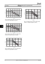
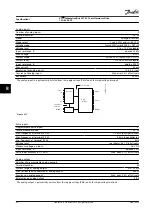
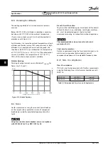
Figure 8.5 Derating Enclosure Sizes E and F, P250 to P630
380–480 V (T5) High overload 150%, 60 AVM

130BX478.10

Iout  [%]

fsw [kHz]

o

70

80

90

1

60

100

110

2

3

4

5

6

7

50 C

o

55 C

0

50

o

45 C

Figure 8.6 Derating Enclosure Sizes E and F, P250 to P630
380–480 V (T5) Normal Overload 110%, 60 AVM

130BX479.10

Iout  [%]

fsw [kHz]

o

70

80

90

1

60

100

110

2

3

4

5

50 C

o

55 C

0

o

45 C

Figure 8.7 Derating Enclosure Sizes E and F, P250 to P630
380–480 V (T5) High overload 150%, SFAVM

130BX480.10

Iout  [%]

fsw [kHz]

o

70

80

90

1

60

100

110

2

3

4

5

50 C
55 C

0

o

45 C

o

50

o

40 C

Figure 8.8 Derating Enclosure Sizes E and F, P250 to P630
380–480 V (T5) Normal Overload 110%, SFAVM

Specifications

VLT

®

 AutomationDrive FC 302 Low Harmonic Drive

132–630 kW

90

Danfoss A/S © Rev. 04/2015 All rights reserved.

MG37A322

8

8

Summary of Contents for VLT AutomationDrive FC 302

Page 1: ...MAKING MODERN LIVING POSSIBLE Installation Manual VLT AutomationDrive FC 302 Low Harmonic Drive 132 630 kW www DanfossDrives com...

Page 2: ......

Page 3: ...c Standards 17 1 6 5 IEEE Harmonic Standards 18 2 Safety 20 2 1 Safety 20 2 2 Qualified Personnel 20 2 3 Safety Precautions 20 3 Installation 21 3 1 Installation Site Checklist 21 3 2 Electrical Insta...

Page 4: ...6 F Frame Line Power Contactors 42 4 8 Control Wiring 42 4 8 1 Control Cable Routing 42 4 8 2 Access to Control Terminals 43 4 8 3 Electrical Installation Control Terminals 43 4 8 4 Electrical Instal...

Page 5: ...60 5 5 Checking Motor Rotation 60 5 6 Local Control Test 60 5 7 System Start up 60 6 Application Examples 61 6 1 Introduction 61 6 2 Application Examples 61 7 Status Messages 68 7 1 Status Display 68...

Page 6: ...pendix A Parameters 106 9 1 Description of Parameters 106 9 2 Frequency Converter Parameter Lists 106 9 3 Active Filter Parameter Lists 112 10 Appendix B 120 10 1 Abbreviations and Conventions 120 Ind...

Page 7: ...ontact the local Danfoss supplier or visit the Danfoss website www danfoss com BusinessAreas DrivesSolutions Documentations Technical Documentation htmfor downloads or additional information The VLT A...

Page 8: ...nt Sensors VLT Drive Main s 3 3 3 CTs Lc Lc Lc Cef Cef Cef Ref Ref Ref Ir Is It 130BB406 11 Figure 1 1 Basic Layout for the Low Harmonic Drive Low harmonic drives are designed to draw an ideal sinusoi...

Page 9: ...ting bracket 18 Fan assembly 6 Power card mounting plate 19 Fan transformer 7 Power card 20 AC input terminals 8 Capacitor bank assembly 21 AC input bus bar 9 Soft charge fuses 22 Input terminal mount...

Page 10: ...fan 5 AC capacitors discharge board 17 DC capacitor bank 6 Line power contactor 18 Current transformer 7 LC inductor 19 RFI differential mode filter 8 AC capacitors 20 RFI common mode filter 9 Line p...

Page 11: ...Fan assembly 6 Power card mounting plate 19 Output motor terminals 7 Power card 20 Current sensor 8 IGBT gate drive card 21 Main AC power input terminals 9 Upper capacitor bank assembly 22 Input term...

Page 12: ...ower disconnect 5 RFI differential mode filter 16 Electrical fuses 6 RFI common mode filter 17 LC inductor 7 Current transformer CT 18 HI inductor 8 Line power bus bars to drive output 19 Power card 9...

Page 13: ...e power line fuses if purchased 3 Line power AC power input terminals Figure 1 6 Frame Size F18 Options Cabinet The options cabinet is not optional for the LHD The ancillary equipment is stored in the...

Page 14: ...om options cabinet 4 Metal oxide varistor MOV 13 RFI differential mode filter 5 AC capacitors discharge board 14 RFI common mode filter 6 LC inductor 15 Line power contactor 7 HI inductor 16 Power car...

Page 15: ...k fan 3 SMPS fuse 9 Fan door cover 4 Optional back AC fuse mounting bracket 10 SMPS fuse 5 Optional middle AC fuse mounting bracket 11 Power card 6 Optional front AC fuse mounting bracket 12 Panel con...

Page 16: ...module 4 MDCIC board 12 Panel connectors 5 Control card 13 DC fuse 6 SMPS fuse and fan fuse 14 Mounting bracket 7 Motor output bus bar 15 DC bus bar 8 Brake output bus bar 16 DC bus bar Figure 1 9 Fra...

Page 17: ...ol the total harmonic distortion on the mains supply Although the harmonic currents do not directly affect electrical energy consumption they generate heat in wiring and transformers and can impact ot...

Page 18: ...ecause of the voltage drop on the impedances of the distribution system Higher impedances result in higher levels of voltage distortion Current distortion relates to apparatus performance and it relat...

Page 19: ...00 3 12 Regulate mains interference generated by connected devices in lower current products EN 50178 Monitors electronic equipment for use in power installations Table 1 6 EN Design Standards for Mai...

Page 20: ...and currents for individual components within the supply network The standard also provides limits for the sum of all loads at the point of common coupling PCC To determine permissible harmonic voltag...

Page 21: ...e 20 ISC IL RSCE h 11 11 h 17 17 h 23 23 h 35 35 h Total demand distortion TDD 20 4 2 0 1 5 0 6 0 3 5 20 50 7 3 5 2 5 1 0 0 5 8 50 100 10 4 5 4 0 1 5 0 7 12 100 1000 12 5 5 5 0 2 0 1 0 15 1000 15 7 0...

Page 22: ...tallation start up and maintenance could result in death or serious injury WARNING UNINTENDED START When the adjustable frequency drive is connected to AC line power the motor may start at any time Th...

Page 23: ...damage Before unpacking the adjustable frequency drive locate it as close as possible to the final instal lation site Compare the model number on the nameplate to what was ordered to verify the prope...

Page 24: ...tilated in and out the back of a Rittal TS8 enclosure for frame size F18 LHD This offers a solution where the backchannel could take air from outside the facility and return the heat losses outside th...

Page 25: ...for minimum 10 minutes External ducts If additional duct work is added externally to the Rittal cabinet the pressure drop in the ducting must be calculated Use the charts below to derate the adjustab...

Page 26: ...ight of the adjustable frequency drive See for the weight of the different frame sizes Maximum diameter for bar is 1 in 2 5 cm The angle from the top of the adjustable frequency drive to the lifting c...

Page 27: ...of anchoring hole dimensions Bottom View D1n D2n 64 5 2 5 20 0 0 8 40 0 1 6 560 0 22 0 327 4 12 9 289 4 11 4 227 8 9 0 246 0 9 7 350 0 13 8 397 3 15 6 240 0 9 4 220 0 8 7 235 0 9 3 42 3 1 7 8X 14 0 0...

Page 28: ...235 0 9 3 40 4 1 6 8X 25 0 1 0 8X 14 0 0 6 330 0 13 0 470 4 18 5 390 0 15 4 246 0 9 7 1 1 Cable entry locations Figure 3 10 Cable Entry Diagram Enclsoure Size D2n Installation VLT AutomationDrive FC 3...

Page 29: ...Bottom view enclosure size E9 1 130BC586 10 1 Cable entry locations Figure 3 11 Cable Entry Diagram E9 Installation Installation Manual MG37A322 Danfoss A S Rev 04 2015 All rights reserved 27 3 3...

Page 30: ...otor cable entry 2 Option enclosure 5 Inverter enclosure 3 Filter enclosure 6 Rectifier enclosure Figure 3 12 Cable Entry Diagram F18 Installation VLT AutomationDrive FC 302 Low Harmonic Drive 132 630...

Page 31: ...3 83 5 3 3 167 0 6 6 8 0 120 2 4 7 MOTOR OUTPUT TERMINALS 130BC603 10 Figure 3 13 Frame Size D13 Terminal Locations Allow for bend radius of heavy power cables NOTICE All D frames are available with s...

Page 32: ...3 5 168 7 6 6 MAINS INPUT TERMINAL MOTOR OUTPUT TERMINAL Figure 3 14 Frame Size E9 Terminal Locations Allow for bend radius of heavy power cables NOTICE All E frames are available with standard input...

Page 33: ...he inverter cabinet No connection terminals are located in the rectifier cabinet Interconnecting bus bars are not shown 1 2 3 4 0 0 0 00 76 4 3 01 128 4 5 05 119 0 4 69 171 0 6 73 294 6 11 60 344 0 13...

Page 34: ...bar 2 34 9 1 4 46 3 1 8 3 86 9 3 4 98 3 3 9 4 122 2 4 8 119 4 7 5 174 2 6 9 171 6 7 1 Disconnect location and related dimensions vary with kilowatt rating Figure 3 16 Input Option Cabinet with Circui...

Page 35: ...18 1 12 5 551 0 21 7 587 0 23 1 635 0 25 0 671 0 26 4 44 40 1 75 244 40 9 62 204 1 8 0 497 1 19 6 572 1 22 5 180 3 7 1 129 1 5 1 1 2 3 1 Front view 2 Left side view 3 Right side view Figure 3 17 Inver...

Page 36: ...Torque Bolt size D Line power Motor 19 40 Nm 168 354 in lbs M10 Load sharing Brake 8 5 20 5 Nm 75 181 in lbs M8 E Line power Motor Load sharing 19 40 Nm 168 354 in lbs M10 Brake 8 5 20 5 Nm 75 181 in...

Page 37: ...Class 20 motor overload protection Overcurrent protection Extra protective equipment such as short circuit protection or motor thermal protection between adjustable frequency drive and motor is requir...

Page 38: ...minimum 16 mm2 10 Low harmonic drive LHD Figure 4 1 EMC correct Installation NOTICE EMC Interference Use screened cables for motor and control wiring Separate the LHD mains input cable motor cable an...

Page 39: ...ble HF impedance Connect the motor cable shield to both the decoupling plate of the adjustable frequency drive and to the metal housing of the motor Make the shield connections with the largest possib...

Page 40: ...ng ELCB relays observe local regulations Relays must be suitable for protection of 3 phase equipment with a bridge rectifier and for a brief discharge on power up 4 5 2 RFI Switch Line power supply is...

Page 41: ...18 of type code The connection cable to the brake resistor must be shielded and the max length from adjustable frequency drive to the DC bar is limited to 82 ft 25 m Terminal No Function 81 82 Brake r...

Page 42: ...oss Lower the IGBT switching frequency Modify the inverter waveform 60 AVM vs SFAVM Install a shaft grounding system or use an isolating coupling between motor and load Use minimum speed settings if p...

Page 43: ...Failure to isolate these connections could result in less than optimum controller and associated equipment performance Because the power wiring carries high frequency electrical pulses it is importan...

Page 44: ...P630 380 500 V Eaton XTCEC14P22B Table 4 9 Recommended Contactors 4 8 Control Wiring 4 8 1 Control Cable Routing Tie down all control wires to the designated control cable routing as shown in Figure...

Page 45: ...nals All terminals to the control cables are located beneath the LCP both filter and adjustable frequency drive LCP They are accessed by opening the door of the unit 4 8 3 Electrical Installation Cont...

Page 46: ...Remove the screwdriver The cable is now mounted in the terminal To remove the cable from the terminal 1 Insert a screwdriver max 0 016x0 1 in 0 4x2 5 mm in the square hole 2 Pull out the cable 130BT3...

Page 47: ...240Vac 2A 24V NPN 0V PNP 0V PNP 24V NPN 19 D IN 24V NPN 0V PNP 27 24V 0V D IN OUT 0V PNP 24V NPN D IN OUT 0V 24V 29 24V NPN 0V PNP 0V PNP 24V NPN 33 D IN 32 D IN 1 2 ON S201 ON 2 1 S202 ON I 0 20mA O...

Page 48: ...27 29 32 33 20 37 24 V DC 0 VDC 130BT107 11 Figure 4 15 Input Polarity of Control Terminals NPN NOTICE To comply with EMC emission specifications shielded armored cables are recommended If using non s...

Page 49: ...es always use shielded motor cable Cable Shielded twisted pair STP Impedance 120 Cable length Max 4000 ft 1200 m including drop lines Max 1 650 ft 500 m station to station Table 4 10 Cable Recommendat...

Page 50: ...rmal motor protection it is also possible to use the MCB 112 PTC thermistor card option This card provides ATEX certification to protect motors in explosion hazardous areas Zone 1 21 and Zone 2 22 Whe...

Page 51: ...1 25 Motor Nominal Speed Table 4 11 Quick Set up Parameters 3 MOTOR NR 1827421 2003 S E005A9 1 5 KW n2 31 5 MIN 400 Y V n1 1400 MIN 50 Hz cos 0 80 3 6 A 1 7L B IP 65 H1 1A 130BT307 10 BAUER D 7 3734 E...

Page 52: ...ers at 10 C 50 F and turn them off at 15 6 C 60 F Cabinet light with power outlet A light mounted on the cabinet interior of F frame frequency converters increases visibility during servicing and main...

Page 53: ...before each motor starter and is off when the incoming power to the frequency converters is off Up to 2 starters are allowed 1 if a 30 A fuse protected circuit is ordered and are integrated into the f...

Page 54: ...Confirm that the supply voltage matches the voltage of the adjustable frequency drive and the motor 5 1 1 Pre start CAUTION Before applying power to the unit inspect the entire installation as detail...

Page 55: ...to comply could result in death or serious injury WARNING UNINTENDED START When the adjustable frequency drive is connected to AC line power the motor may start at any time The adjustable frequency dr...

Page 56: ...uency 5 3 0 24 kWh counter Table 5 2 Legend to Figure 5 1 Display Area Frequency Converter Side B Display menu keys Menu keys are used for menu access for parameter set up toggling through status disp...

Page 57: ...the LCP memory To download data to another adjustable frequency drive connect the LCP to that unit and download the stored settings Restoring factory default settings does not change data stored in t...

Page 58: ...r than normal Manual initialisation does not reset the following frequency converter information Parameter 15 00 Operating hours Parameter 15 03 Power ups Parameter 15 04 Over Temps Parameter 15 05 Ov...

Page 59: ...minal 27 Digital Input at factory default Otherwise select No Operation in parameter 5 12 Terminal 27 Digital Input For adjustable frequency drives with an optional bypass no jumper wire is required b...

Page 60: ...parameter 1 53 Model Shift Frequency Example 1 If the motor oscillates at 5 Hz and dynamics performance is required at 15 Hz set parameter 1 53 Model Shift Frequency to 10 Hz Example 2 If the applicat...

Page 61: ...ended choice for applications where the motor is rotating at slow speed e g windmilling in fan applications parameter 2 06 Parking Current and parameter 2 07 Parking Time can be adjusted Increase the...

Page 62: ...2 Scroll to parameter 1 28 Motor Rotation Check and press OK 3 Scroll to 1 Enable The following text appears Note Motor may run in wrong direction 4 Press OK 5 Follow the on screen instructions NOTIC...

Page 63: ...insulation to meet PELV insulation requirements Parameters FC 24 V 24 V D IN D IN D IN COM D IN D IN D IN D IN 10 V A IN A IN COM A OUT COM 12 13 18 19 20 27 29 32 33 37 50 53 54 55 42 39 130BB929 10...

Page 64: ...ent 20 mA parameter 6 14 Terminal 53 Low Ref Feedb Value 0 RPM parameter 6 15 Terminal 53 High Ref Feedb Value 1 500 RPM Default Value Notes comments Table 6 4 Analog Speed Reference Current Parameter...

Page 65: ...e Parameters FC 24 V 24 V D IN D IN D IN COM D IN D IN D IN D IN 10 V A IN A IN COM A OUT COM 12 13 18 19 20 27 29 32 33 37 50 53 54 55 42 39 130BB934 10 Function Setting parameter 5 10 Terminal 18 Di...

Page 66: ...er 6 15 Terminal 53 High Ref Feedb Value 1 500 RPM Default Value Notes comments Table 6 9 Speed Reference using a Manual Potentiometer Parameters FC 24 V 24 V D IN D IN D IN COM D IN D IN D IN D IN 10...

Page 67: ...above Table 6 11 RS 485 Network Connection Parameters 130BB686 12 VLT 24 V 24 V D IN D IN D IN COM D IN D IN D IN 10 V A IN A IN COM A OUT COM 12 13 18 19 20 27 29 32 33 50 53 54 55 42 39 A53 U I D I...

Page 68: ...rameter 13 12 Comparator Value 90 parameter 13 51 SL Controller Event 22 Comparator 0 parameter 13 52 SL Controller Action 32 Set digital out A low parameter 5 40 Function Relay 80 SL digital output A...

Page 69: ...al 19 Digital Input 11 Start reversing parameter 1 71 Start Delay 0 2 parameter 1 72 Start Function 5 VVC FLUX Clockwise parameter 1 76 Start Current Im n parameter 2 20 Release Brake Current App depe...

Page 70: ...drive issuing an alarm A warning clears by itself when the abnormal condition is removed 7 2 2 Alarm Trip An alarm is issued when the frequency converter is tripped that is the frequency converter su...

Page 71: ...ly voltage and supply currents to the adjustable frequency drive WARNING 5 DC link voltage high The intermediate circuit voltage DC is higher than the high voltage warning limit The limit is dependent...

Page 72: ...rogramming if 1 93 Thermistor Resource matches sensor wiring If using a KTY Sensor check the programming of parameter 1 95 KTY Sensor Type parameter 1 96 KTY Thermistor Resource and parameter 1 97 KTY...

Page 73: ...g can be disabled in parameter 14 53 Fan Monitor 0 Disabled Troubleshooting Check fan resistance Check soft charge fuses WARNING 24 External fan fault The fan warning function is an extra protective f...

Page 74: ...munication fault The serial communication bus on the communication option card is not working WARNING ALARM 36 Mains failure This warning alarm is only active if the supply voltage to the adjustable f...

Page 75: ...e with control board hardware 5124 Option in slot B Hardware incompatible with control board hardware 5125 Option in slot C0 Hardware incompatible with control board hardware 5126 Option in slot C1 Ha...

Page 76: ...nt Limit Ensure that motor data in parameters 1 20 to 1 25 are set correctly Increase the current limit if necessary Ensure that the system can operate safely at a higher limit WARNING 60 External int...

Page 77: ...rt when the fault is cleared WARNING 76 Power unit set up The required number of power units does not match the detected number of active power units Troubleshooting When replacing an F frame module t...

Page 78: ...ates which power module generated the alarm 1 left most inverter module 2 middle inverter module in F12 or F13 frame sizes 2 right inverter module in F10 or F11 frame sizes 2 second adjustable frequen...

Page 79: ...the adjustable frequency drive has been replaced Troubleshooting Reset the adjustable frequency drive for normal operation WARNING 251 New typecode The power card or other components have been replac...

Page 80: ...ed see also Table 7 2 Alarms that are trip locked offer additional protection meaning that the line power supply must be switched off before the alarm can be reset After being switched back on the uni...

Page 81: ...fault X 301 SC cont fault X 302 Cap overcurrent X X 303 Cap ground fault X X 304 DC overcurrent X X 305 Mains freq limit X 308 Resistor temp X X 309 Power ground fault X X 311 Switch freq limit X 312...

Page 82: ...rrent DC overcurrent Password Protection 19 00080000 524288 Resistor temp Resistor temp Reserved 20 00100000 1048576 Power ground fault Power ground fault Reserved 21 00200000 2097152 Switch freq limi...

Page 83: ...not set to off Possible correction Increase parameter 8 03 Control Timeout Time Change parameter 8 04 Control Timeout Function WARNING 23 Internal fan fault Internal fans have failed due to defect har...

Page 84: ...en exchanged The filter type code must be restored in the EEPROM Select the correct type code in parameter 14 23 Typecode Setting according to the label on the unit Remember to select Save to EEPROM t...

Page 85: ...on control voltage terminal 12 or 50 or at control terminals Check the 24 V control voltage supply for terminals 12 13 to 20 39 or 10 V supply for terminals 50 to 55 Wire the terminals properly Wrong...

Page 86: ...nal Motor running in wrong direction Motor rotation limit Check that parameter 4 10 Motor Speed Direction is programmed correctly Program correct settings Active reversing signal Check if a reversing...

Page 87: ...the adjustable frequency drive Rotate input power leads into the adjustable frequency drive one position A to B B to C C to A If imbalance leg stays on same input terminal it is a problem with the uni...

Page 88: ...251 304 304 381 381 463 Continuous at 460 480 V A 231 291 291 348 348 427 Max pre fuses1 A 400 500 630 Max cable size Motor mm2 AWG2 2x185 2x300 mcm Line power mm2 AWG2 Load sharing mm2 AWG2 Brake mm2...

Page 89: ...us at 460 480 V A 436 531 531 580 580 667 667 718 Max pre fuses1 A 700 900 Max cable size Motor mm2 AWG2 4x240 4x500 mcm Line power mm2 AWG2 Load sharing mm2 AWG2 Brake mm2 AWG2 2x185 2x350 mcm Total...

Page 90: ...V A 711 759 759 867 867 1022 1022 1129 Max pre fuses1 A 1600 2000 Max cable size Motor mm2 AWG2 8 x 150 8 x 300 mcm Line power mm2 AWG2 8 x 240 8 x 500 mcm Brake mm2 AWG2 4 x 185 4 x 350 mcm Total LH...

Page 91: ...st be allowed for 5 8 1 2 Derating for Temperature The frequency converter automatically derates the switching frequency switching type or output current under certain load or ambient conditions as de...

Page 92: ...V T5 Normal Overload 110 60 AVM 130BX479 10 Iout fsw kHz o 70 80 90 1 60 100 110 2 3 4 5 50 C o 55 C 0 o 45 C Figure 8 7 Derating Enclosure Sizes E and F P250 to P630 380 480 V T5 High overload 150 SF...

Page 93: ...9 0 5 5 443 0 17 4 611 0 24 1 663 5 26 1 843 5 33 2 1568 3 61 7 807 3 31 8 677 3 26 7 929 2 36 6 377 8 14 9 130BE140 10 251 0 9 9 221 0 8 7 301 9 11 9 369 0 14 5 664 4 26 2 864 4 34 0 Figure 8 9 Enclo...

Page 94: ...6 184 5 7 3 369 14 5 534 5 21 641 17 25 2 747 83 29 4 854 5 33 6 1914 7 75 4 1781 4 70 1 1562 4 61 5 1504 59 2 470 92 18 5 130 5 1 130 5 1 160 6 3 251 89 9 9 130BE139 10 Figure 8 10 Enclosure Size D2...

Page 95: ...84 5 30 9 969 0 38 2 1153 5 45 4 160 0 6 3 160 0 6 3 248 0 9 8 725 0 28 5 1043 0 41 1 160 0 6 3 493 5 19 4 1200 0 47 2 130BC171 10 Figure 8 11 Enclosure Size E9 Specifications Installation Manual MG37...

Page 96: ...130BC174 11 2792 0 110 605 8 24 Figure 8 12 Enclosure Size F18 Front and Side View Specifications VLT AutomationDrive FC 302 Low Harmonic Drive 132 630 kW 94 Danfoss A S Rev 04 2015 All rights reserve...

Page 97: ...torque constant torque maximum 160 for 1 m Starting torque maximum 180 up to 0 5 s Overload torque constant torque maximum 160 for 1 m Percentage relates to nominal torque of the unit Cable lengths an...

Page 98: ...BA117 10 Figure 8 13 Pulse inputs Programmable pulse inputs 2 Terminal number pulse 29 33 Max frequency at terminal 29 33 110 kHz push pull driven Max frequency at terminal 29 33 5 kHz open collector...

Page 99: ...le relay outputs 2 Relay 01 Terminal number 1 3 break 1 2 make Max terminal load AC 1 1 on 1 3 NC 1 2 NO resistive load 240 V AC 2A Max terminal load AC 15 1 inductive load cos 0 4 240 V AC 0 2 A Max...

Page 100: ...61000 6 3 4 EN 55011 IEC 61800 3 EMC standards immunity EN 61800 3 EN 61000 6 1 2 EN 61000 4 2 EN 61000 4 3 EN 61000 4 4 EN 61000 4 5 EN 61000 4 6 Control card performance Scan interval 5 ms Control c...

Page 101: ...ter lowest rated supply voltage If AC line voltage exceeds the filter highest rated voltage the filter continues to work but harmonic mitigation performance is reduced The filter does not cut out unti...

Page 102: ...NPN 19 V DC Voltage level logic 1 NPN 14 V DC Maximum voltage on input 28 V DC Input resistance Ri approx 4 k All digital inputs are galvanically isolated from the supply voltage PELV and other high...

Page 103: ...z Response time reactive and harmonic 0 5 ms Settling time reactive current control 20 ms Settling time harmonic current control 20 ms Overshoot reactive current control 10 Overshoot Harmonic current...

Page 104: ...akers on the supply side as protection in case of component break down inside the adjustable frequency drive first fault NOTICE Using fuses and or circuit breakers ensures compliance with IEC 60364 fo...

Page 105: ...A 700 V 6 9URD33D08A0900 20 630 32 900 355 170M6013 900 A 700 V 6 9URD33D08A0900 20 630 32 900 400 170M6013 900 A 700 V 6 9URD33D08A0900 20 630 32 900 Table 8 7 Enclosure size E Mains Fuses 380 480 V...

Page 106: ...tor Controller Fuses Enclosure size Bussmann PN1 Rating Alternative fuses F LPJ 30 SP or SPI 30 A 600 V Any listed Class J dual element time delay 30 A Table 8 13 30 A Fuse Protected Terminal Fuse Enc...

Page 107: ...For fastening hardware described in this manual use the torque values in Table 8 20 These values are not intended for fastening IGBTs See the instructions included with those replacement parts for co...

Page 108: ...y converter All parameters are grouped by name indicating the function of the parameter group All parameters are listed by name and number in this manual 9 2 Frequency Converter Parameter Lists Append...

Page 109: ...ference 2 06 Parking Current 2 07 Parking Time 2 1 Brake Energy Funct 2 10 Brake Function 2 11 Brake Resistor ohm 2 12 Brake Power Limit kW 2 13 Brake Power Monitoring 2 15 Brake Check 2 16 AC brake M...

Page 110: ...ss CL Feedback 2 Resource 7 3 Process PID Ctrl 7 30 Process PID Normal Inverse Control 7 31 Process PID Anti Windup 7 32 Process PID Start Speed 7 33 Process PID Proportional Gain 7 34 Process PID Int...

Page 111: ...ings 15 10 Logging Source 15 11 Logging Interval 15 12 Trigger Event 15 13 Logging Mode 15 14 Samples Before Trigger 15 2 Historic Log 15 20 Historic Log Event 15 21 Historic Log Value 15 22 Historic...

Page 112: ...er Marker Tolerance Window 33 22 Slave Marker Tolerance Window 33 23 Start Behavior for Marker Sync 33 24 Marker Number for Fault 33 25 Marker Number for Ready 33 26 Velocity Filter 33 27 Offset Filte...

Page 113: ...are Readouts 99 13 Idle time 99 14 Paramdb requests in queue 99 15 Secondary Timer at Inverter Fault 99 16 No of Current Sensors 99 17 tCon1 time 99 18 tCon2 time 99 19 Time Optimize Measure 99 2 Heat...

Page 114: ...o a conversion figure used when writing or reading using an active filter Conv index 100 75 74 70 67 6 5 4 3 2 1 0 1 2 3 4 5 6 Conv factor 1 3 600 00 0 3 60 0 60 1 60 1 000 0 00 100 00 0 10 00 0 1 000...

Page 115: ...Display Line 1 3 Small 30120 All set ups TRUE Uint16 0 23 Display Line 2 Large 30100 All set ups TRUE Uint16 0 24 Display Line 3 Large 30121 All set ups TRUE Uint16 0 25 My Personal Menu ExpressionLim...

Page 116: ...ll set ups TRUE Uint8 5 15 Terminal 33 Digital Input 91 DC Contactor All set ups TRUE Uint8 5 16 Terminal X30 2 Digital Input 0 No operation All set ups TRUE Uint8 5 17 Terminal X30 3 Digital Input 0...

Page 117: ...Delay 5000 ms 1 set up TRUE 3 Uint16 8 37 Max Inter Char Delay 25 ms 1 set up TRUE 3 Uint16 8 5 Digital Bus 8 53 Start Select 3 Logic OR All set ups TRUE Uint8 8 55 Set up Select 3 Logic OR All set up...

Page 118: ...set ups FALSE 0 VisStr 20 15 42 Voltage 0 N A All set ups FALSE 0 VisStr 20 15 43 Software Version 0 N A All set ups FALSE 0 VisStr 5 15 44 Ordered Typecode String 0 N A All set ups FALSE 0 VisStr 40...

Page 119: ...Inverter Thermal 0 All set ups FALSE 0 Uint8 16 36 Inv Nom Current ExpressionLimit All set ups FALSE 2 Uint32 16 37 Inv Max Current ExpressionLimit All set ups FALSE 2 Uint32 16 39 Control Card Temp 3...

Page 120: ...LSE Uint8 300 25 CT Polarity 0 Normal 2 set ups FALSE Uint8 300 26 CT Placement 1 Load Current 2 set ups FALSE Uint8 300 29 Start Auto CT Detection 0 Off All set ups FALSE Uint8 300 3 Compensation 300...

Page 121: ...1 Uint16 301 11 Estimated THD of Voltage 0 0 All set ups Uint16 301 12 Power Factor 0 00 N A All set ups TRUE 2 Uint16 301 13 Cos phi 0 00 N A All set ups TRUE 2 Int16 301 14 Leftover Currents 0 0 A A...

Page 122: ...frequency converter IP Ingress protection LCP Local control panel N A Not applicable PM N Nominal motor power PCB Printed circuit board PE Protective earth PELV Protective extra low voltage Regen Reg...

Page 123: ...Brake Chopper 39 Braking 71 Branch circuit protection 102 Bus termination switch 49 C Cable Motor cable 35 Cable length and cross section 37 Cable lengths and cross sections 95 100 Cabling 37 CE Comp...

Page 124: ...37 38 52 53 H Hand on 55 Harmonic mitigation performance 99 Harmonics 6 Harmonics Analysis 15 Harmonics 15 16 17 distortion 15 Overload prevention 15 Voltage harmonics 16 Heater 50 Heatsink 73 High vo...

Page 125: ...rrent protection 35 Overload protection 21 P Parallel connection of motors 47 Parameter menu structure 107 PELV 61 Phase loss 69 Planning installation site 21 Point of common coupling 16 Potentiometer...

Page 126: ...re limits 52 Terminal functions 40 Terminal Locations Frame Size D13 29 Terminals Output terminal 52 Terminal 53 48 Terminal 54 48 Thermal motor protection 70 Thermistor 61 70 Torque 34 70 Torque char...

Page 127: ...Index Installation Manual MG37A322 Danfoss A S Rev 04 2015 All rights reserved 125...

Page 128: ...brochures or other printed material Danfoss reserves the right to alter its products at any time without notice provided that alterations to products already on order shall not require material chang...

Reviews: