


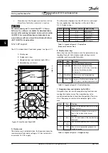


6 Application Examples
6.1 Introduction
The examples in this section are intended as a quick
reference for common applications.
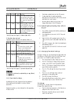
•
Parameter settings are the regional default values
unless otherwise indicated (selected in
parameter 0-03 Regional Settings
).
•
Parameters associated with the terminals and
their settings are shown next to the drawings.
•
Required switch settings for analog terminals A53
or A54 are also shown.
NOTICE!
When using the optional STO feature, a jumper wire may
be required between terminal 12 (or 13) and terminal 37
for the frequency converter to operate with factory
default programming values.
NOTICE!
The following examples refer only to the frequency
converter control card (right LCP),
not
the filter.
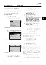
6.2 Application Examples
CAUTION
Thermistors must use reinforced or double insulation to
meet PELV insulation requirements.
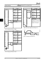
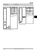
Parameters
FC
+24 V
+24 V
D IN
D IN
D IN
COM
D IN
D IN
D IN
D IN
+10 V
A IN
A IN
COM
A OUT
COM
12
13
18
19
20
27
29
32
33
37
50
53
54
55
42
39
130BB929.10
Function
Setting
parameter 1-29
Automatic Motor
Adaptation
(AMA)
[1] Enable
complete
AMA
parameter 5-12
Terminal 27
Digital Input
[2]* Coast
inverse
*=Default Value
Notes/comments:
Parameter
group
1–2* Motor Data
must be
set according to motor
Table 6.1 AMA with T27 Connected
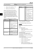
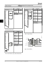
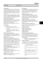
Parameters
FC
+24 V
+24 V
D IN
D IN
D IN
COM
D IN
D IN
D IN
D IN
+10 V
A IN
A IN
COM
A OUT
COM
12
13
18
19
20
27
29
32
33
37
50
53
54
55
42
39
130BB930.10
Function
Setting
parameter 1-29
Automatic Motor
Adaptation
(AMA)
[1] Enable
complete
AMA
parameter 5-12
Terminal 27
Digital Input
[0] No
operation
*=Default Value
Notes/comments:
Parameter
group
1–2* Motor Data
must be
set according to motor
Table 6.2 AMA without T27 Connected
Application Examples
Installation Manual
MG37A322
Danfoss A/S © Rev. 04/2015 All rights reserved.
61
6
6


