


Synchronizing controller
MG.10.N4.02 - VLT is a registered Danfoss trademark
5
Mechanical brake control
The Synchronizing controller has a 24V dc digital output (Output 4) to control an electromechanical
brake; this is very useful in applications when a motor (shaft) must be kept in the same position for a
longer time. This is usually the case in hoisting applications. The brake output will be active (low) in
case of an error and when synchronization is stopped, that means whenever motor control is switched
off. The brake signal can be delayed when switched on and off in two individual parameters (P. 755
“brake on delay” and P. 756 “brake off delay”).
Please note that the brake output is kept low in VLT mode (input 8 = high). That means the brake must
be opened for example by means of the VLT mechanical brake function in set-up 2.
Tips and tricks for synchronization tasks
When configuring the drives to be synchronized please keep in mind that the ratios should be of
integer size. When using gear it is also important to know the number of teeth of the various gear
stages (ask the gear manufacturer) as gears are normally set up with infinite gear ratios.
When calculating the ratios between master and slave you must either use the figure PI for both of
them or not use PI at all.
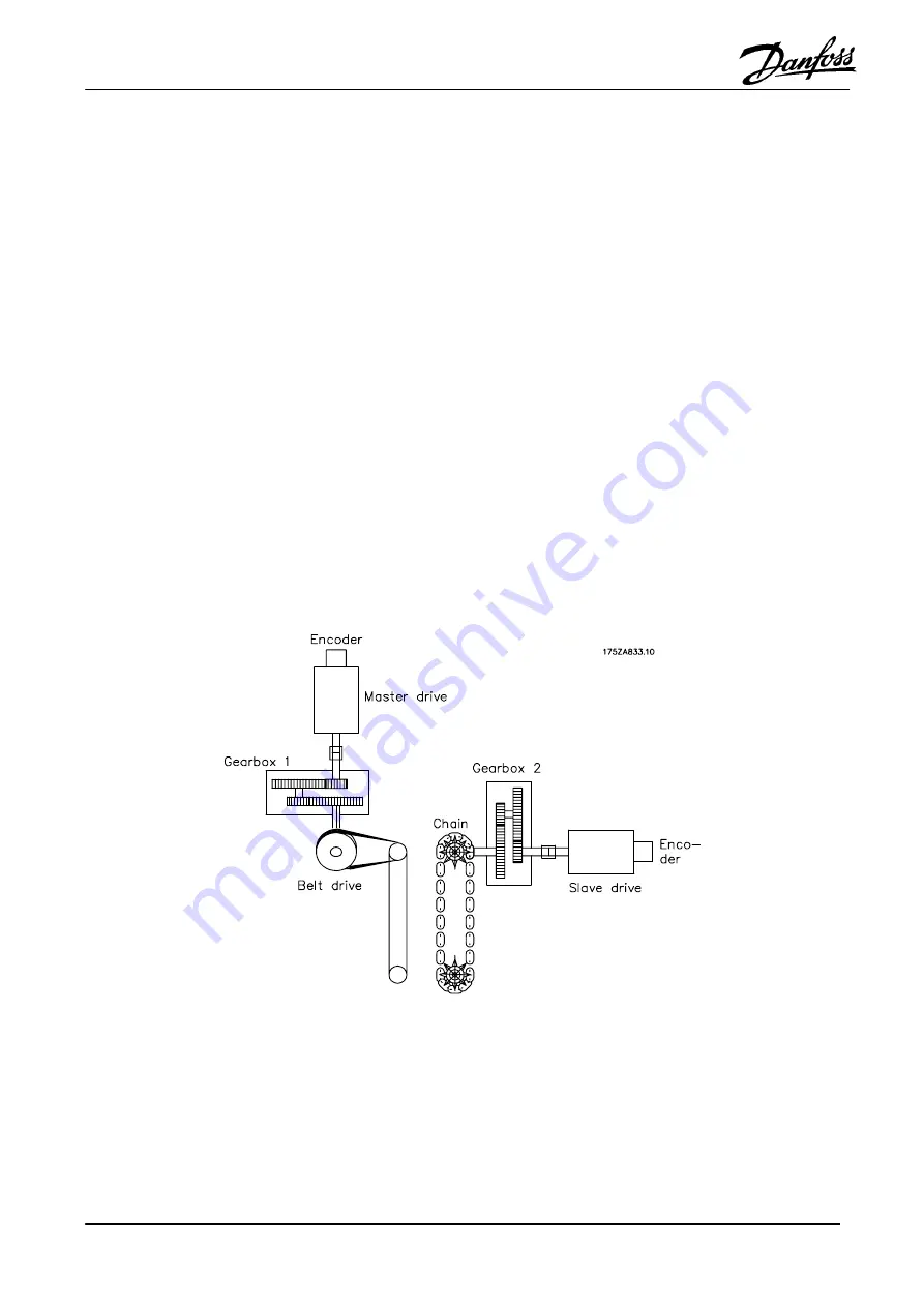
Example:
A master drive with a 4-pole motor and an incremental encoder of 1024 increments/revolution works
on a 2-stage gear. i is specified to be 30.33. At the gear output, a belt ratio of 40:20 is placed, driving a
conveyor belt on the drive side with a diameter of 102mm.
Via a 3-stage gear (i is specified to be 46,54) the slave drive is connected to an 8-toothed chain
conveyor with a tooth pitch of 200mm.
Figure 1: Calculation example