


Synchronizing controller
MG.10.N4.02 - VLT is a registered Danfoss trademark
17
60
±
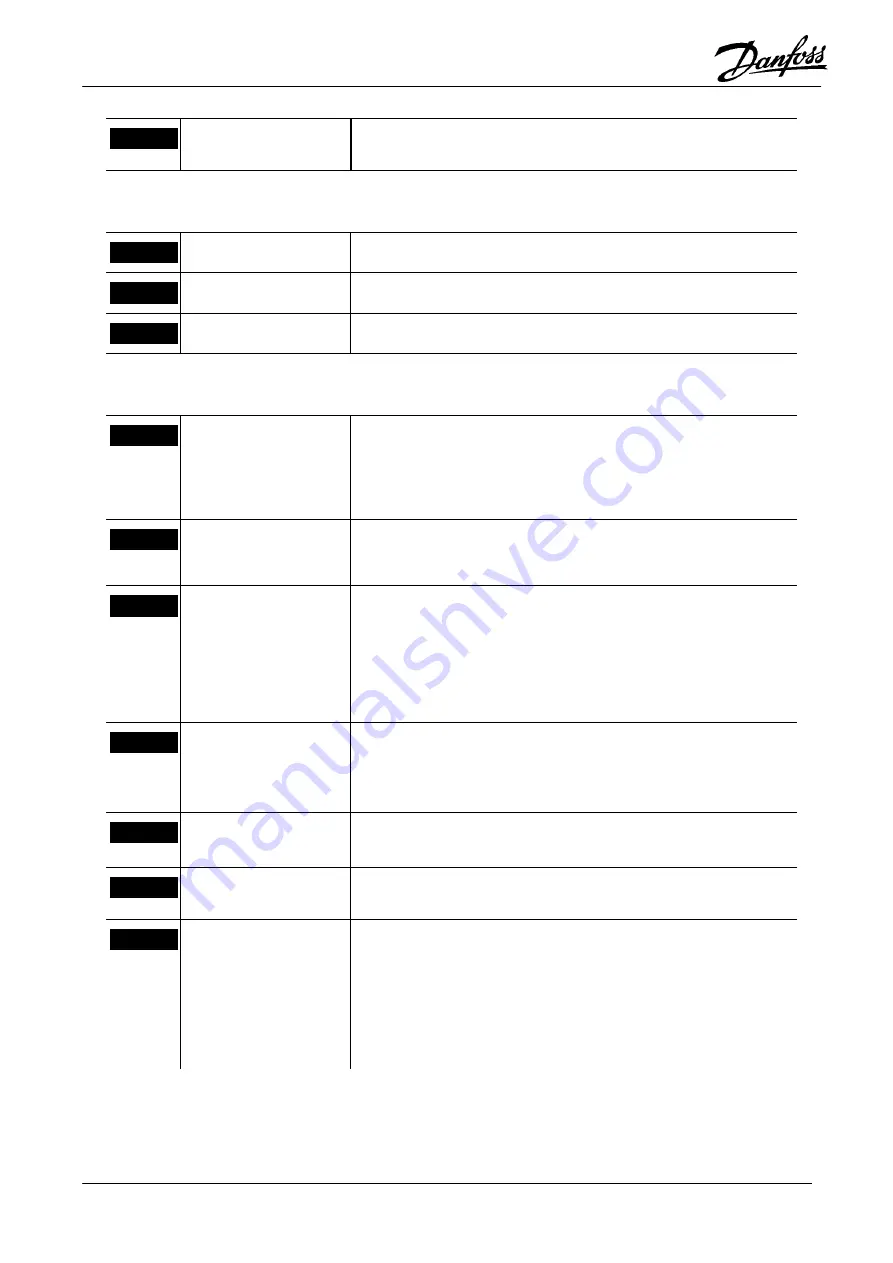
20mA-In
Serves as reference input for the virtual master if “1” is selected in
Parameter 748.
Standard RS485-Interface
61
Ground RS485
Not used
68
RS485-P
Not used
69
RS485-N
Not used
Option card MK3A
1
I1 - Sync-Start
Synchronous operation; Program 2:
Start and stop of synchronization. Input 1 must be toggled if
synchronization was interrupted by an error or by input 27 (motor
coast). Behaviour at stop can be selected via parameter 725.
2
I2 - Take over gear
ratio
Synchronous operation; Program 2:
Activates the gear ratio selected at Terminals 16 and 17.
3
I3 - Start/Stop virtual
master
Test run; Program 1:
Start test run with virtual master.
Synchronous operation; Program 2: The virtual master is accele-
rated up to the set pulse frequency, or stopped, with the set ramp
time.
4
I4 - Saving the settings “1” = All 7xx parameters are saved. Input 4 must be reset to “0” to
end the save procedure. Parameter 710 will be 1 and output 5 will
be high while saving. Note: saving is only possible if all inputs,
except input 27, are low. Input 27 must be high.
5
I5 - Master marker
input
When using external marker signal for the master drive it must be
connected to this input.
6
I6 - Slave marker input When using external marker signal for the slave drive it must be
connected to this input.
7
I7 - Measuring of the
master marker interval
Home switch
Test run; Program 1:
Measuring of the master marker interval is started.
Synchronous operation; Program 2:
If a home position is to be attained, the home switch must be
connected here. The signal must show a rising edge