1
English
RWEYQ8PY1
RWEYQ10PY1
RWEYQ16PY1
RWEYQ18PY1
RWEYQ20PY1
RWEYQ24PY1
RWEYQ26PY1
RWEYQ28PY1
RWEYQ30PY1
VRVW
III
System air conditioner
Installation manual
CONTENTS
1. SAFETY PRECAUTIONS ....................................................... 1
2. INTRODUCTION...................................................................... 2
2-1. Combination ...................................................................... 2
2-2. Standard operation limit .................................................... 3
2-3. Standard supplied accessories ......................................... 3
2-4. Option accessory .............................................................. 3
2-5. Technical and electrical specifications .............................. 3
3. SELECTION OF LOCATION ................................................... 3
4. INSPECTING AND HANDLING THE UNIT ............................. 4
5. UNPACKING AND PLACING THE UNIT................................. 4
6. WATER PIPING WORK........................................................... 4
7. HANDLING OF THE BRAZED PLATE TYPE HEAT
EXCHANGER .......................................................................... 4
7-1. When designing the equipment ........................................ 4
7-2. Before starting a test run................................................... 5
7-3. Daily service and maintenance ......................................... 5
7-4. Water quality ..................................................................... 5
7-5. Maintenance of plate type heat exchanger ....................... 5
8. FIELD WIRING ........................................................................ 6
8-1. Optional parts.................................................................... 6
8-2. Power circuit and cable requirements ............................... 6
8-3. General ............................................................................. 6
8-4. Examples .......................................................................... 7
8-5. In case of a local setting ................................................... 8
9. REFRIGERANT PIPING .......................................................... 9
9-1. Selection of piping material ............................................... 9
9-2. Protection against contamination when installing pipes.... 9
9-3. Pipe connection ................................................................ 9
9-4. Connecting the refrigerant piping .................................... 10
9-5. Example of connection.................................................... 11
9-6. Air tight test and vacuum drying...................................... 13
9-7. Pipe insulation................................................................. 13
9-8. Checking of device and installation conditions ............... 13
9-9. Additional refrigerant charge ........................................... 13
9-10. Shutoff valve operation procedure ................................ 14
10. CHECKS AFTER INSTALLATION......................................... 14
11. TEST RUN ............................................................................. 14
11-1. Air discharge ................................................................. 14
11-2. Before turn on the power supply ................................... 14
11-3. Check operation ............................................................ 14
11-4. Check of normal operation ............................................ 15
12. CAUTION FOR REFRIGERANT LEAKS ............................... 16
Important information regarding the refrig-
erant used
This product contains fluorinated greenhouse gases covered by the
Kyoto Protocol. Do not vent gases into the atmosphere.
Refrigerant type:R410A
GWP
(1)
value:
1975
(1)
GWP = global warming potential
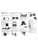
Please fill in with indelible ink,
➀
the factory refrigerant charge of the product,
➁
the additional refrigerant amount charged in the field and
➀
+
➁
the total refrigerant charge
on the refrigerant charge label supplied with the product.
The filled out label must be adhered in the proximity of the product
charging port (e.g. onto the inside of the service cover).
(2)
In case of multiple outdoor systems, only 1 label must be adhered,
mentioning the total factory refrigerant charge of all outdoor units
connected on the refrigerant system.
1.
SAFETY PRECAUTIONS
Please read these “SAFETY PRECAUTIONS” carefully before
installing air conditioning unit and be sure to install it correctly.
After completing installation, conduct a trial operation to check for
faults and explain to the customer how to operate the air conditioner
and take care of it with the aid of the operation manual. Ask the cus-
tomer to store the installation manual along with the operation man-
ual for future reference.
This air conditioner comes under the term “appliances not
accessible to the general public”.
〈
Safety Precaution
〉
VRV System is a class A product. In a domestic environment this
product may cause radio interference in which case the user may be
required to take adequate measures.
Meaning of WARNING and CAUTION notices
WARNING
.....Failure to follow these instructions properly may
result in personal injury or loss of life.
CAUTION
......Failure to observe these instructions properly
may result in property damage or personal
injury, which may be serious depending on the
circumstances.
WARNING
• Ask your dealer or qualified personnel to carry out installation
work.
Do not attempt to install the air conditioner yourself. Improper
installation may result in water leakage, electric shocks or fire.
• Install the air conditioner in accordance with the instructions in
this installation manual.
Improper installation may result in water leakage, electric shocks
or fire.
• When installing the unit in a small room, take measures against to
keep refrigerant concentration from exceeding allowable safety
limits in the event of refrigerant leakage.
Contact the place of purchase for more information. Excessive
refrigerant in a closed ambient can lead to oxygen deficiency.
• Be sure to use only the specified accessories and parts for instal-
lation work.
Failure to use the specified parts may result in the unit falling,
water leakage, electric shocks or fire.
• Install the air conditioner on a foundation strong enough to with-
stand the weight of the unit.
A foundation of insufficient strength may result in the equipment
falling and causing injury.
• Carry out the specified installation work after taking into account
strong winds, typhoons or earthquakes.
Failure to do so during installation work may result in the unit fall-
ing and causing accidents.
3
5
6
2
1
4
1
factory refrigerant charge
of the product:
see unit name plate
(2)
2
additional refrigerant
amount charged in the
field
3
total refrigerant charge
4
Contains fluorinated
greenhouse gases
covered by the Kyoto
Protocol
5
outdoor unit
6
refrigerant cylinder and
manifold for charging
01_EN_3P153897-8L.fm Page 1 Friday, July 11, 2008 5:04 PM
Summary of Contents for VRV-WIII
Page 22: ...3P153897 8L EM08A055 0808 HT...