


English
4
3.
Remote controller
4.
Cool/heat selector
5.
Personal computer or radio
If the electric wave of AM broadcasting is particularly weak, keep
distances of 3m or more and use conduit tubes for power and
transmission lines.
2.
Water quality
Water containing high level of foreign materials may cause the
corrosion of heat exchanger and piping or scale accumulation.
Use water satisfying “7-4 Water quality”.
3.
Cooling tower
Use a closed type cooling tower without fail. (Open type tower
cannot be used.)
4.
Strainer
Install a strainer (an optional accessory) without fail at the inlet
of water piping. (If sands, wastes, rust particles, etc. are mixed
in the water circulation system, damage to the plate type heat
exchanger may be caused by the corrosion of metal materials
and clogging of the heat exchanger.)
5.
The refrigerant R410A itself is nontoxic, nonflammable and is
safe. If the refrigerant should leak however, its concentration
may exceed the allowable limit depending on room size. Due to
this it could be necessary to take measures against leakage.
Refer to the chapter “CAUTION FOR REFRIGERANT LEAKS”.
4.
INSPECTING AND HANDLING THE
UNIT
At delivery, the package should be checked and any damage should
be reported immediately to the carrier claims agent.
When handling the unit, take into account the following:
1.
Fragile, handle the unit with care.
Keep the unit upright in order to avoid compressor damage.
2.
Choose the path along which the unit is to be brought in ahead of
time.
3.
In order to prevent any damage to the unit during installation, use
slings (cloth) or patch plates and lift the unit referring to figure 4.
4.
Lift the unit preferably with a crane and 2 belts of at least 4m long.
5.
Use patch plates or clothes where the belt may hit the casing in
order to prevent the casing from being damaged.
6.
Be sure use the standard supplied accessories and dedicated
parts as installation parts.
(Refer to figure 4)
1.
Patch plates or clothes
2.
Belt sling
Note
•
Use belt sling of 20mm width or less which adequately bears the
weight of the product.
5.
UNPACKING AND PLACING THE UNIT
• Make sure the area around the machine drains properly by setting
up drainage grooves around the foundation.
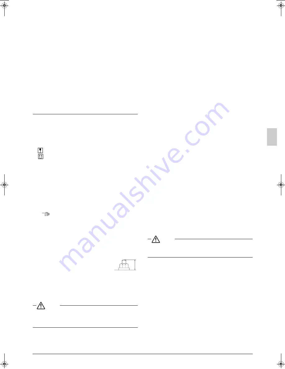
• Make sure the unit is installed level on a sufficiently strong base to
prevent vibration and noise.
• Secure the unit to its base using foundation bolts. (Use four com-
mercially available M12-type foundation bolts, nuts, and washers.)
• The foundation bolts should be inserted 20 mm.
• Fix 4 foundation bolts.
• Support the unit with the foundation which is
larger than the hatched area shown in figure 5.
(Refer to figure 5)
1.
Front side
2.
Position of foundation bolts
3.
Hole for a foundation bolt
(
φ
17 holes at 4 corners)
4.
Avoid such a foundation where the unit is supported by
4 corner points.
Caution
• When installing the unit closely contacting the wall for any
unavoidable reason, arrange so that no vibration from the unit
may be transmitted to the wall surface by insulating the vibra-
tion using cushions, etc.
6.
WATER PIPING WORK
• The water pressure resistance of water piping of this outside unit
is 1.96 MPa.
• The pipe connection on the unit is made of stainless steel.
Connecting a water pipe made of a material other than stainless
steel may result in corrosion of the pipe.
Take preventive measures as necessary, for example by insulat-
ing the connection on the water pipe.
• The connection port for water piping is located in the front. The
connection ports for drain piping are located in the front and back.
When using the back port, change the cast iron plug from the
back to the front and securely close it.
• Because of indoor use, carry out piping work in such a way no
water may drop on the outer plate.
• Drain piping should be short and have a slant downwards.
The diameter of drain pipe should be the same as the diameter of
unit connection (1/2B) or larger.
• The diameter of water pipe should be the same as the diameter of
unit connection (1-1/4) or larger.
• Install an air purge valve in the midway of the water piping to pre-
vent cavitation.
• After completing the drain piping work, make sure that the water
runs smoothly without any clogging by dust.
• Do not connect the drain outlet to the water outlet.
• Install a strainer (an optional accessory) in the inlet of water piping
within a distance of 1.5 m from the outside unit.
(If sand, waste or rust particles are mixed in the water circulation
system, metal materials will become corrosive.)
• Install insulation up to the base of heat exchanger as shown in the
figure 6.
• Install a gate valve for chemical cleaning in an easy position to handle.
• Use water pipes complied with the local and national codes.
• Run the water pump to flush inside of water piping.
Then, clean the strainer.
• If there is a possibility of freezing, take measures to prevent freezing.
• Tighten securely the connection of water piping and socket with
tightening torque of 300 N·m or less.
(If a larger torque is applied, the unit may be damaged.)
(Refer to figure 6)
1.
Air parge
2.
Outlet of water
3.
Inlet of water
4.
Gate valve
5.
Water piping socket
6.
Water piping
7.
Insulation
8.
Heat exchanger
9.
Strainer (an optional accessory)
10.
Drain valve
11.
Connection port to draining piping
12.
Insulation cover
13.
80 mm or less
7.
HANDLING OF THE BRAZED PLATE
TYPE HEAT EXCHANGER
Caution
A brazed plate type heat exchanger is used for this unit.
Because its structure is different from a conventional type heat
exchanger, it must be handled in a different manner.
7-1 When designing the equipment
1.
Install a strainer (an optional accessory) at the water inlet side
adjacent to the outside unit in order to prevent any foreign mate-
rials such as dust, sand, etc. from entering.
2.
Depending on the water quality, scale may stick to the plate type
heat exchanger. In order to remove this scale, it is necessary to
clean it at a regular interval using chemicals. To this end, install a
gate valve in the water piping. Set up a piping connection port on
the piping between this gate valve and the outside unit for clean-
ing by chemicals.
3.
For the purpose of cleaning and water drain off from the outside
unit (water draining during a long period of non-use in winter,
draining upon starting of season-off), install an “air discharge plug”
and a “water draining plug” at the inlet/outlet ports of water piping.
In addition, install an “automatic air discharging valve” at the top of
riser piping or at the top of a portion where air tends to stay.
4.
Independent of the piping inlet of the outside unit, install a clean-
able strainer at a portion close to the pump piping inlet.
20
01_EN_3P153897-8L.fm Page 4 Friday, July 11, 2008 5:04 PM
Summary of Contents for VRV-WIII
Page 22: ...3P153897 8L EM08A055 0808 HT...


