


English
14
Additional refrigerant charge procedure (2)-by Additional refrig-
erant charge operation
About the system settings for additional refrigerant charge operation,
refer to the [Service Precaution] label attached on the electric box
cover in the outside unit.
1.
Fully open all shutoff valves (valve A and valve B in the figure
24 must be left fully closed).
2.
After ten minutes, fully close liquid line shutoff valve and then,
open the valve by turning 180°.
Start the additional refrigerant charge operation.
See [Service precautions] Label for detail.
If it is difficult to charge the refrigerant additionally, decrease
the water temperature or warm the refrigerant tank.
(Warm the refrigerant tank with a stupe or a warm hot water of
40 degrees or less.)
3.
After the system is charged with a specified amount of refrigerant,
press the RETURN button (BS3) on the PC board (A1P) in the
outside unit to stop the additional refrigerant charge operation.
4.
Immediately open both liquid-side and gas-side shutoff valve.
(If do not open the shutoff valve immediately, liquid seal may
cause the pipe to burst.)
Note
•
Procedures for charging additional refrigerant.
(Refer to figure 24)
9-10 Shutoff valve operation procedure
Caution
Do not open the shutoff valve until 1-6 of “9-8 Checking of device
and installation conditions” are completed. If the shutoff valve is
left open without turning on power, it may cause refrigerant to
buildup in the compressor, leading to insulation degradation.
Opening shutoff valve
1.
Remove the cap and turn the valve counterclockwise with the
hexagon wrench (JISB4648).
2.
Turn it until the shaft stops.
Do not apply excessive force to the shutoff valve. Doing so may
break the valve body, as the valve is not a backseat type. Always
use the hexagon wrench.
3.
Make sure to tighten the cap securely.
Closing shutoff valve
1.
Remove the cap and turn the valve clockwise with the hexagon
wrench (JISB4648).
2.
Securely tighten the valve until the shaft contacts the main body
seal.
3.
Make sure to tighten the cap securely.
∗
For the tightening torque, refer to the table on the bellow.
Tightening torque
(Refer to figure 25)
1.
Service port
2.
Cap
3.
Hexagon hole
4.
Shaft
5.
The main body seal
〈
Caution
〉
• Do not damage the cap sealing.
• Always use a charge hose for service port connection.
• After tightening the cap, check that no refrigerant leaks are present.
• After working, securely tighten the cover of service port without
fail by specified torque.
• When loosening a flare nut, always use two wrenches in combi-
nation. When connecting the piping, always use a spanner and
torque wrench in combination to tighten the flare nut.
• When connecting a flare nut, coat the flare (inner and outer faces)
with ether oil or ester oil and hand-tighten the nut 3 to 4 turns as
the initial tightening.
• Do not forget to open the stop valve before starting operation.
(Refer to figure 26)
1.
Remove the cap and turn the valve counter clocwise with
the hexagon wrenches until it stops.
2.
HP/LP gas shutoff valve
3.
Liquid shutoff valve
4.
Suction gas shutoff valve
5.
Never remove the partition flange for any reason.
6.
Full close on the suction gas side
10. CHECKS AFTER INSTALLATION
After the installation, check the following.
1.
The shutoff valve
Make sure that the shutoff valve (both liquid and gas) is opened.
See the “
Shutoff valve operation procedure
” in chapter 9-10.
2.
Additional refrigerant charge
The amount of refrigerant to be added to the unit should be written
on the included “Added Refrigerant” plate and attached to the rear
side of the front cover.
3.
Installation date
Be sure to keep record of the installation date on the sticker on the
EL. COMPO. BOX cover according to EN60335-2-40.
11. TEST RUN
Caution
After completing installation, be sure to open the shutoff valve.
(Operating the unit with the valve shut will break the compressor.)
11-1 Air discharge
• Running the heat source water pump, carry out air discharge
process until the water comes out from the air discharge hole of
local piping.
(For the operation to be done for the first time after installation,
you need to perform a checking operation.)
11-2 Before turn on the power supply
• Close the EL. COMPO. BOX cover securely before turning on power.
• Make settings for outside unit PC board (A1P) after power-on and
check the LED display from inspection door that is on the
EL. COMPO. BOX cover.
11-3 Check operation
(For the operation to be done for the first time after installation,
you need to perform a checking operation according to this guideline
without fail. Otherwise, Abnormal Code “U3” appears and normal
operation cannot be carried out.)
Shutoff
valve size
Tightening torque N-m (Turn clockwise to close)
Shaft (valve body)
Cap
(valve lid)
Service
port
Flare nut
Gas side
accessory
pipe (1)
Liquid
side
5.4-6.6
Hexagonal
wrench 4 mm
13.5-16.5 11.5-13.9 32.7-39.9
_
Gas
side
27-33
Hexagonal
wrench 10 mm
36-44
11.5-13.9
_
22-28
(1)Check the connection of interlock circuit
The outside unit cannot be operated if the
interlock circuit has not been connected.
(2)As necessary, configure the system set-
tings onsite by using the dipswitch (DS1)
and push button switches (BS1 to 5) on the
outside unit PC board (A1P).
After this, close the cover of electrical box.
Always perform configuration after turning
ON the power. To learn the setting method,
refer to the [Service Precautions] label
attached at the cover of electrical box shown
in the figure 27. Remember, the actual set-
tings you have made must be recorded on
the [Service Precautions] label.
(3)Turn ON the power to the outside units
and indoor units.
Make sure to turn ON the power 6 hours before
starting the operation. This is necessary to
warm the crankcase by the electric heater.
(4)Start the heat source water pump and fill
the heat source water in the outside unit.
The outside unit cannot be operated if the
heat source water pump is not running.
(5)Make sure that the temperature of heat
source water is kept within the operation
range (10 - 45°C).
The outside unit cannot be operated at a
temperature outside the operation range.
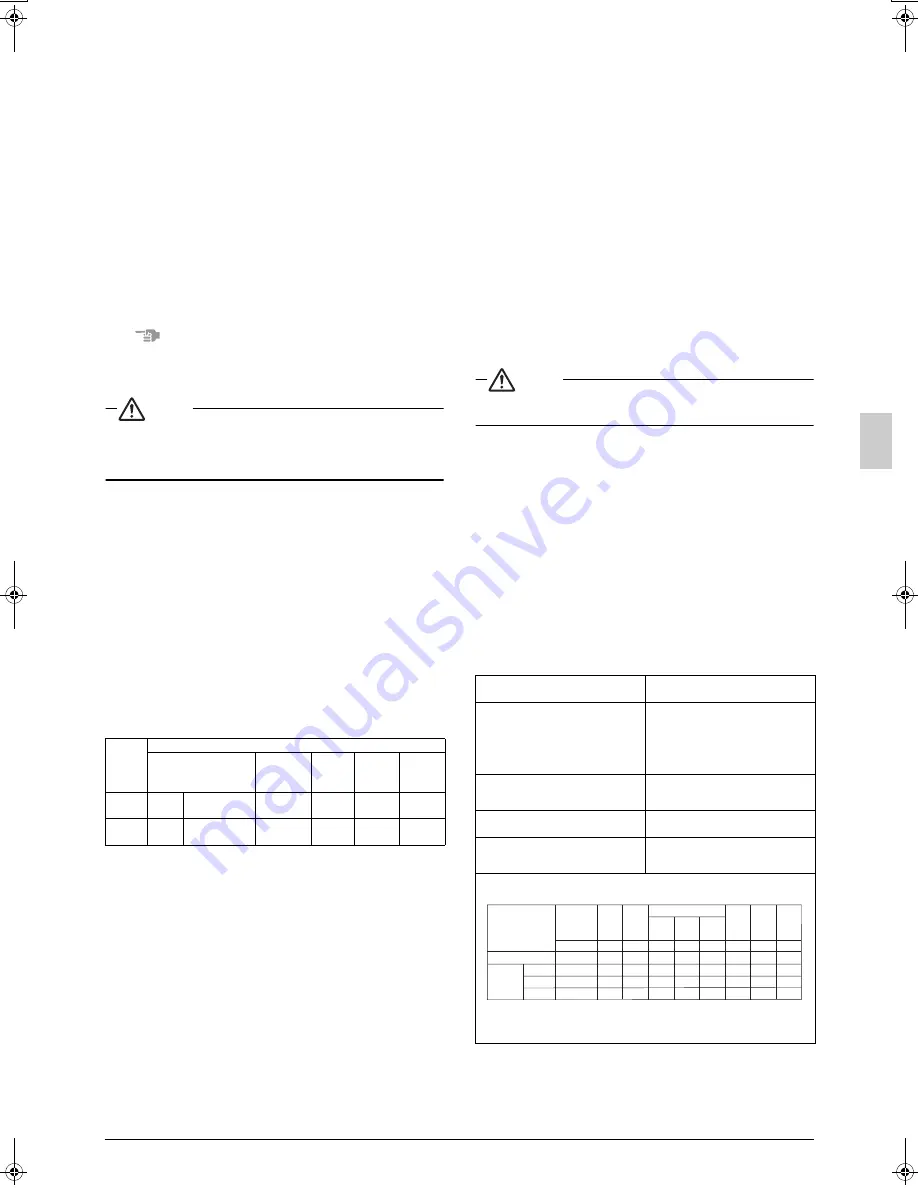
(6)Check the LED on the PC board (A1P) in the outside unit to see if the data transmission is
performed normally.
LED display
(Default status
before delivery)
One outside unit installed
When multiple
outside unit
installed (
∗
)
Master station
Sub station 1
Sub station 2
Microcomputer
operation
monitor
Page
HAP
H1P
H2P
H3P
H4P
H5P
H6P
H7P
H8P
Ready/
Error
Cooler/heater changeover
Individual
Bulk
(parent)
Bulk
(child)
Low
noise
Demand
Multi
LED display:
OFF
ON
Blinking
(
∗
) The master unit is the outside unit to which the transmission wiring for the
indoor units is connected. The other outside units are sub units.
j
i
i
i
j
j
j
j
h
h
h
h
h
h
h
h
h
h
h
h
h
h
h
h
h
h
h
h
h
h
h
h
h
h
h
h
i
h
j
01_EN_3P153897-8L.fm Page 14 Friday, July 11, 2008 5:04 PM
Summary of Contents for VRV-WIII
Page 22: ...3P153897 8L EM08A055 0808 HT...


