


English
8
• The wiring to the indoor units must be connected to the F1/F2
(To IN/D UNIT) terminals on the PC board in the outside unit.
Field line connection: Power supply wiring and transmission
wiring
Make sure to connect the power wire to the power terminal block and
fix it using attached clamp as shown in figure 15 and 19.
(Refer to figure 15)
1.
Power supply
(3N~, 380-415V)
2.
Branch switch, overcurrent breaker
3.
Grounding wire
4.
Earth leakage breaker
5.
Attach insulation sleeves.
6.
Power supply terminal block
7.
Grounding terminal
8.
Retain the ground wires along with the power wires using
the accessory clamp (A).
9.
Grounding wire
10.
When wiring, do not allow the ground wires to contact
the compressor lead wires. If the wires contact each
other, adverse effects may occur to other units.
11.
When connecting two wires to one terminal, ensure that
the crimp-style terminals face with each other back to
back.
Moreover, make sure that the wire of the smaller gauge
is located above.
12.
Terminal block
13.
Crimp-style terminal
14.
Wire gauge: Small
15.
Wire gauge: Large
(Refer to figure 19)
1.
Intake for power supply wiring, pump operation output
(high voltage) and ground wiring.
2.
Intake for power supply jumper wiring and ground jumper
wiring. (Only for jumping the powrer supply.)
3.
HP/LP shutoff valve (high temperature part)
4.
Retain the power supply wiring, pump operation output
(high voltage) and ground wiring with the accessory
clamp(A).
5.
Insert the accessory clamp (B) in the hole of the fixing
plate for stop valve.
6.
Power supply wiring, pump operation output (high volt-
age) and ground wiring.
7.
Approximately 50mm
8.
Power supply jumper wiring and ground jumper wiring.
9.
Retain the power supply wiring, pump operation output
(high voltage) and ground wiring with the accessory
clamp (B) to prevent them from touching with the stop
valve for discharge gas.
10.
Use the through hole cover for power jumper supply by
cutting the hatched area.
11.
Hatched area
12.
Insert the accessory clamp (B) in the hole of the bottom
of electrical box.
13.
Intake for transmission wiring. (low voltage)
14.
Make sure to provide for a downward loop in the trans-
mission wiring right in front of the location where the wir-
ing is to be fixed over the topplate of the switch box. This
in order to prevent that condensate drips off the wiring
into the switch box.
15.
Fix the transmission wiring to resin clamps with the
accessory clamps (A)
16.
Pass the transmission wiring (low voltage) through the
wire clip.
17.
Retain the power supply wiring, pump operation output
(high voltage) and ground wiring to the bottom of electri-
cal box with the accessory clamp (B)
18.
Do not bundle the power supply jumper wiring.
Caution
〈
Precautions when laying power wiring
〉
Use crimp-style terminals for connections to the power terminal block.
When none are available, follow the instructions below.
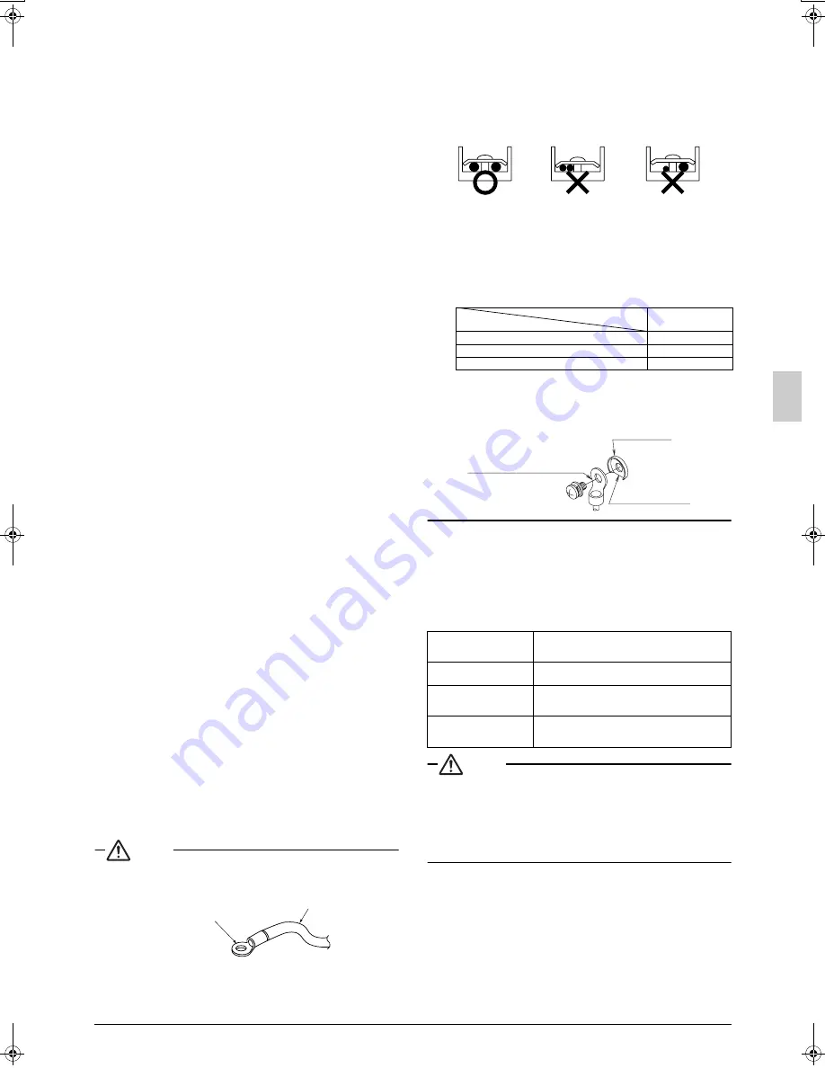
•
Do not connect wiring of different size to the power terminal
block. (Slack in the power wiring may cause abnormal heat.)
•
When connecting wiring which is the same thickness, do as
shown in the figure below.
•
For wiring, use the designated power wire and connect firmly,
then secure to prevent outside pressure being exerted on the
terminal board.
•
Use an appropriate screwdriver for tightening the terminal
screws. A screwdriver with a small head will strip the head and
make proper tightening impossible.
•
Over-tightening the terminal screws may break them.
•
See the table below for tightening torque for the terminal
screws.
〈
Precautions when connecting the ground
〉
When pulling the ground wire out, wire it so that it comes through
the cut out section of the cup washer. (An improper ground con-
nection may prevent a good ground from being achieved.)
8-5 In case of a local setting
If necessary, do the local settings as mentioned in the table below.
For setting, refer to the plate “Cares to be taken in servicing” attached
to the cover of electrical box.
Typical local settings
∗
For other settings than mentioned in the table below, refer to the
equipment design materials and service manual.
Caution
A separate adapter (sold separately as an accessory) for exter-
nal control of an outside unit becomes necessary when doing a
demand operation from an external instruction, setting of cool-
ing and heating through a centralized remote controller for cool-
ing and heating (sold separately as an accessory) and setting of
centralized interlock. For details, refer to the manual attached to
the adapter.
Power wire
Crimp-style terminal
Tightening torque
(N · m)
M5 (Power terminal block)
2.0-3.0
M5 (Ground)
3.2-3.9
M3.5 (transmission wiring terminal block)
0.8-0.97
(1)Setting of switching between
cooling and heating
This setting is done when switching between cooling and
heating is performed by a switching remote controller (sold
separately as an accessory) installed on the outside unit.
(2)Setting to prohibit
sequenced start
This setting is done when the outside units are not started
in a sequenced order.
(3)Setting of centralized inter-
lock Setting of external
demand
These settings are done when the interlocks are connected
in a lump-sum manner or when performing a demand oper-
ation by external instruction.
(4)Setting of abnormal display
when interlock contact is
OFF
This setting is done when making an abnormal display (HJ)
on a remote controller when the interlock contact is OFF
(when the heat source water pump is not operated).
Connect same-
size wiring
to both sides.
It is forbidden to
connect two to
one side.
It is forbidden to
connect wiring of
different size.
Crimp-style terminal
Cup washer
Cut out section
01_EN_3P153897-8L.fm Page 8 Friday, July 11, 2008 5:04 PM
Summary of Contents for VRV-WIII
Page 22: ...3P153897 8L EM08A055 0808 HT...


