


Si39-504
Specifications
Specifications
31
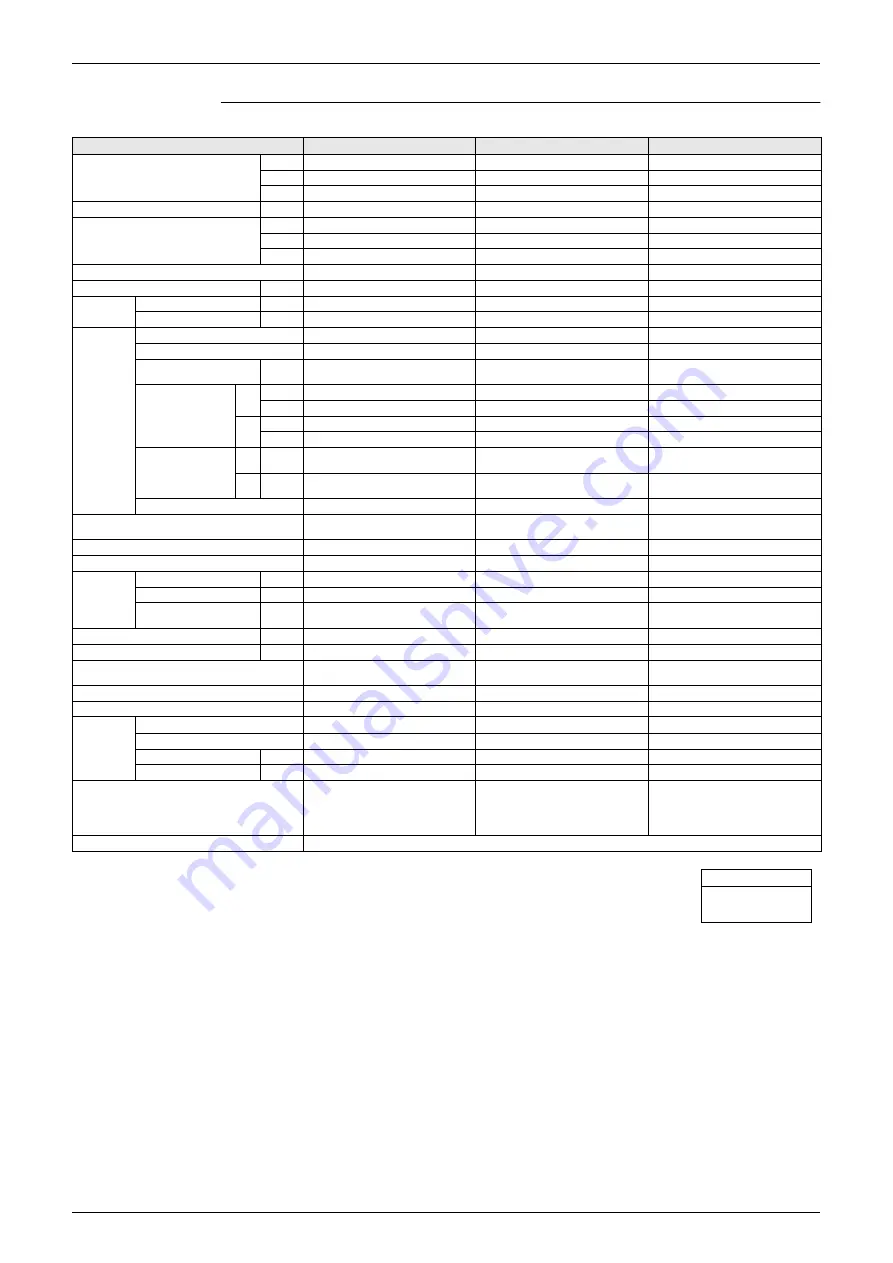
Ceiling Mounted Built-in Type
Notes:
1 Indoor temp. : 27°CDB, 19.5°CWB / outdoor temp. : 35°CDB / Equivalent piping length : 7.5m, level
difference : 0m.
2 Indoor temp. : 27°CDB, 19.0°CWB / outdoor temp. : 35°CDB / Equivalent piping length : 7.5m, level
difference : 0m.
3 Indoor temp. : 20°CDB / outdoor temp. : 7°CDB, 6°CWB / Equivalent piping length : 7.5m, level difference :
0m. (Heat pump only)
4 External static pressure is changeable to change over the connectors inside electrical box, this pressure
means
“High static pressure-Standard -Low static pressure”.
5 Capacities are net, including a deduction for cooling (an additional for heating) for indoor fan motor heat.
6 Anechoic chamber conversion value, measured at a point 1.5m downward from the unit center. These
values are normally somewhat higher during actual operation as a result of ambient conditions.
Model
FXSQ40MVE
FXSQ50MVE
FXSQ63MVE
1 Cooling Capacity (19.5°CWB)
kcal/h
4,000
5,000
6,300
Btu/h
16,000
19,800
24,900
kW
4.7
5.8
7.3
2 Cooling Capacity (19.0°CWB)
kW
4.5
5.6
7.1
3 Heating Capacity
kcal/h
4,300
5,400
6,900
Btu/h
17,100
21,500
27,300
kW
5.0
6.3
8.0
Casing
Galvanized Steel Plate
Galvanized Steel Plate
Galvanized Steel Plate
Dimensions: (H×W×D)
mm
300×700×800
300×700×800
300×1,000×800
Coil (Cross
Fin Coil)
Rows×Stages×Fin Pitch
mm
3×14×1.75
3×14×1.75
3×14×1.75
Face Area
m²
0.132
0.132
0.221
Fan
Model
D18H2A
D18H2A
2D18H2A
Type
Sirocco Fan
Sirocco Fan
Sirocco Fan
Motor Output × Number of
Units
W
65×1
85×1
125×1
Air Flow Rate (H/L)
50
Hz
m³/min
11.5/9
15/11
21/15.5
cfm
406/318
530/388
741/547
60
Hz
m³/min
11.5/9
15/11
21/14
cfm
406/318
530/388
741/494
4
External Static
Pressure
50
Hz
Pa
88-49-20
88-59-29
88-49-20
60
Hz
Pa
88-29-10
88-41-10
122-66-10
Drive
Direct Drive
Direct Drive
Direct Drive
Temperature Control
Microprocessor Thermostat for
Cooling and Heating
Microprocessor Thermostat for
Cooling and Heating
Microprocessor Thermostat for
Cooling and Heating
Sound Absorbing Thermal Insulation Material
Glass Fiber
Glass Fiber
Glass Fiber
Air Filter
Resin Net (with Mold Resistant)
Resin Net (with Mold Resistant)
Resin Net (with Mold Resistant)
Piping
Connections
Liquid Pipes
mm
φ
6.4 (Flare Connection)
φ
6.4 (Flare Connection)
φ
9.5 (Flare Connection)
Gas Pipes
mm
φ
12.7 (Flare Connection)
φ
12.7 (Flare Connection)
φ
15.9 (Flare Connection)
Drain Pipe
mm
VP25
(External Dia. 32 Internal Dia. 25)
VP25
(External Dia. 32 Internal Dia. 25)
VP25
(External Dia. 32 Internal Dia. 25)
Machine Weight (Mass)
kg
30
31
41
6 Sound Level (H/L) (220V)
dBA
38/32
41/36
42/35
Safety Devices
Fuse.
Thermal Protector for Fan Motor.
Fuse.
Thermal Protector for Fan Motor.
Fuse.
Thermal Protector for Fan Motor.
Refrigerant Control
Electronic Expansion Valve
Electronic Expansion Valve
Electronic Expansion Valve
Connectable Outdoor Unit
R-410A M(A) Series
R-410A M(A) Series
R-410A M(A) Series
Decoration
Panel
(Option)
Model
BYBS45DJW1
BYBS45DJW1
BYBS71DJW1
Panel Color
White (10Y9/0.5)
White (10Y9/0.5)
White (10Y9/0.5)
Dimensions: (H×W×D)
mm
55×800×500
55×800×500
55×1,100×500
Weight
kg
3.5
3.5
4.5
Standard Accessories
Operation Manual. Installation
Manual. Paper Pattern for Installation.
Drain Hose. Clamp Metal. Insulation
for Fitting. Sealing Pads. Clamps.
Screws. Washers.
Operation Manual. Installation
Manual. Paper Pattern for Installation.
Drain Hose. Clamp Metal. Insulation
for Fitting. Sealing Pads. Clamps.
Screws. Washers.
Operation Manual. Installation
Manual. Paper Pattern for Installation.
Drain Hose. Clamp Metal. Insulation
for Fitting. Sealing Pads. Clamps.
Screws. Washers.
Drawing No.
C : 3D039431
Conversion Formulae
kcal/h=kW×860
Btu/h=kW×3412
cfm=m³/min×35.3
Summary of Contents for VRV II RXYQ5MATL
Page 53: ...Specifications Si39 504 42 Specifications...
Page 115: ...Outline of Control Indoor Unit Si39 504 104 Function...
Page 161: ...Field Setting Si39 504 150 Test Operation...
Page 172: ...Si39 504 Troubleshooting by Remote Controller Troubleshooting 161...
Page 266: ...Si39 504 Piping Diagrams Appendix 255 RXYQ8MA 10MA 12MAYL E TL E 3D048033A...
Page 267: ...Piping Diagrams Si39 504 256 Appendix RXYQ14MA 16MAYL E TL E 3D048034A...
Page 271: ...Wiring Diagrams for Reference Si39 504 260 Appendix RXYQ8MA 10MA 12MAYL E 3D047088C...
Page 272: ...Si39 504 Wiring Diagrams for Reference Appendix 261 RXYQ14MA 16MAYL E 3D047089C...
Page 273: ...Wiring Diagrams for Reference Si39 504 262 Appendix 2 1 2 RXYQ MATL E RXYQ5MATL E 3D049059A...
Page 274: ...Si39 504 Wiring Diagrams for Reference Appendix 263 RXYQ8MA 10MA 12MATL E 3D049060A...
Page 275: ...Wiring Diagrams for Reference Si39 504 264 Appendix RXYQ14MA 16MATL E 3D049061A...
Page 283: ...Wiring Diagrams for Reference Si39 504 272 Appendix FXCQ40M 50M 80M 125MVE 3D039557A...
Page 285: ...Wiring Diagrams for Reference Si39 504 274 Appendix FXKQ25M 32M 40M 63MVE 3D039564B...
Page 289: ...Wiring Diagrams for Reference Si39 504 278 Appendix FXMQ40M 50M 63M 80M 100M 125MVE 3D039620B...
Page 290: ...Si39 504 Wiring Diagrams for Reference Appendix 279 FXMQ200M 250MVE 3D039621B...
Page 291: ...Wiring Diagrams for Reference Si39 504 280 Appendix FXHQ32M 63M 100MVE 3D039801D...
Page 292: ...Si39 504 Wiring Diagrams for Reference Appendix 281 FXAQ20M 25M 32MVE 40M 50M 63MVE 3D034206C...
Page 309: ...Selection of Pipe Size Joints and Header Si39 504 298 Appendix Note 1...
Page 315: ...Method of Replacing The Inverter s Power Transistors and Diode Modules Si39 504 304 Appendix...